A sprue basin for step pouring system

A pouring system and sprue basin technology, which is applied in casting molding equipment, metal processing equipment, casting mold components, etc., can solve the problems of high production cost and difficult operation, and achieve low cost, good slag blocking effect and simple operation Effect

Active Publication Date: 2020-11-10
KOCEL EQUIP
View PDF8 Cites 0 Cited by
  • Summary
  • Abstract
  • Description
  • Claims
  • Application Information

AI Technical Summary

Problems solved by technology

[0004] The invention overcomes the problems of difficult operation and high production cost caused by the production of multiple sprue pots in the prior art, and provides a sprue pot for a stepped gating system and its use method

Method used


Image

  • A sprue basin for step pouring system
  • A sprue basin for step pouring system
  • A sprue basin for step pouring system

Examples


Embodiment Construction

[0031] In order to enable those skilled in the art to better understand the technical solutions of the present invention, the present invention will be further described in detail below in conjunction with specific examples. Please note that the embodiments described below are exemplary only for explaining the present invention, and should not be construed as limiting the present invention. If no specific technique or condition is indicated in the examples, it shall be carried out according to the technique or condition described in the literature in this field or according to the product specification.

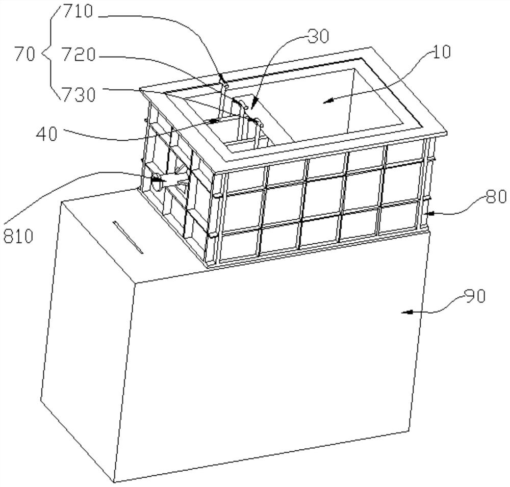
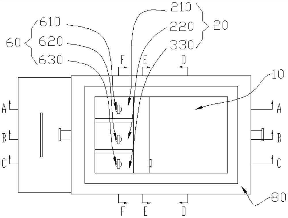
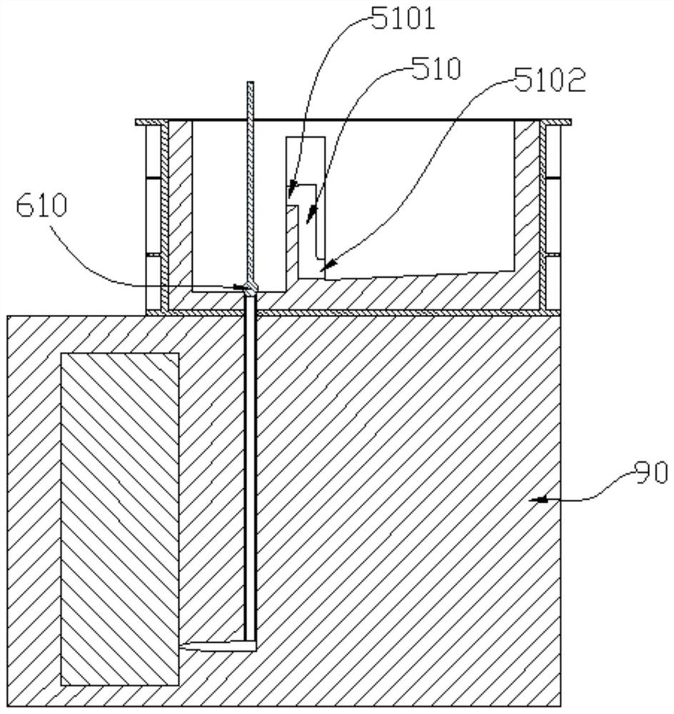
[0032] Such as Figure 1-Figure 8 The sprue pot for a stepped pouring system shown includes a pot body and a water outlet 60, and a stop body 30 is arranged in the pot body to divide the pot body into a liquid inlet chamber 10 and a liquid outlet chamber 20; A dividing dam 40 is provided in the liquid chamber 20 to divide the liquid outlet chamber 20 into three liquid outlet...


PUM


Abstract

The invention relates to a pouring basin for a stepped pouring system. The pouring basin comprises a basin body and water outlets. The basin body is internally provided with a stop body and divided into a liquid inlet cavity and a liquid outlet cavity. The liquid outlet cavity is internally provided with separation dams and divided into two or more liquid outlet cavity bodies, namely the first liquid outlet cavity body and the second liquid outlet cavity body. The stop body is internally provided with stepped connection channels which enable the liquid inlet cavity to communicate with the liquid outlet cavity. The first stepped connection channel is used for enabling the liquid inlet cavity to communicate with the first liquid outlet cavity body, and the second stepped connection channel is used for enabling the liquid inlet cavity to communicate with the second liquid outlet cavity body. The first water outlet is formed in the bottom of the first liquid outlet cavity body, and the second water outlet is formed in the bottom of the second liquid outlet cavity body. The lower portion of the first water outlet and the lower portion of the second water outlet communicate with corresponding sprues. The invention further relates to an application method of the pouring basin for the stepped pouring system. By means of the pouring basin, the problem that multiple pouring basins are not synchronous in pouring is solved; and the pouring basin is easy to operate and low in cost.

Description

technical field [0001] The invention relates to a sprue basin for casting, in particular to a sprue basin for a stepped gating system and a method for using the same. Background technique [0002] The sprue basin is connected to the top of the sprue to receive and introduce the molten metal, and the sprue basin can make the molten metal reach a suitable flow rate before flowing into the sprue. For iron castings, there must be a certain amount of liquid and liquid depth in the sprue basin to prevent the liquid metal from breaking off during the pouring process, thereby reducing impurities such as dross and molten slag from entering the cavity, and preventing the generation of eddies. It is conducive to the smooth flow of molten metal. [0003] For large castings, in order to facilitate feeding, a stepped gating system is often used. On the premise of ensuring that the molten metal enters the cavity smoothly, the temperature field of the molten iron is suitable, which is cond...

Claims


Application Information

Patent Timeline
Patent Type & Authority Patents(China)
IPC IPC(8): B22C9/08
CPCB22C9/082
Inventor 彭凡宋亮苏少静
Owner KOCEL EQUIP
Why Eureka
Try Eureka