Adjustable steering outdoor electronic display screen
A display and electronic technology, which is applied to instruments, identification devices, supporting machines, etc., can solve the problem that the display screen cannot adjust the steering, and achieve the effect of ensuring rotation flexibility, ensuring stability, and reducing friction.
- Summary
- Abstract
- Description
- Claims
- Application Information
AI Technical Summary
Problems solved by technology
Method used
Image
Examples
Embodiment 1
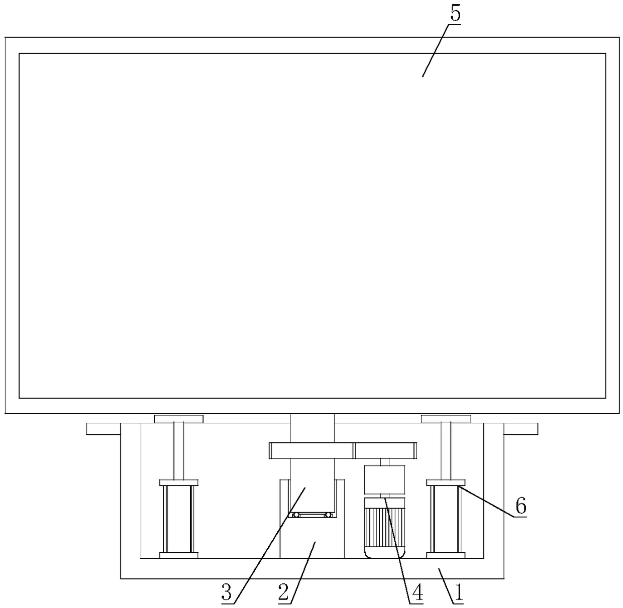
[0024] The outdoor electronic display screen with adjustable steering is characterized in that it includes a base 1, a connecting seat 2 is fixed on the base 1, a groove body 21 is arranged on the connecting seat 2, and a support rod 3 is set inside the groove body 21 of the connecting seat 2 A driving mechanism 4 for driving the support rod 3 to rotate is installed on the base 1 , and a display screen main body 5 is fixed on the other end of the support rod 3 .
[0025] The driving mechanism 4 of the present invention can drive the support rod 3 to rotate, and then the support rod 3 can rotate relative to the connecting seat 2 . During the rotation of the support rod 3, the main body of the display screen 5 can be driven to turn, and the steering of the main body of the display screen 5 can be adjusted according to the situation, so that the present invention has the best viewing angle.
Embodiment 2
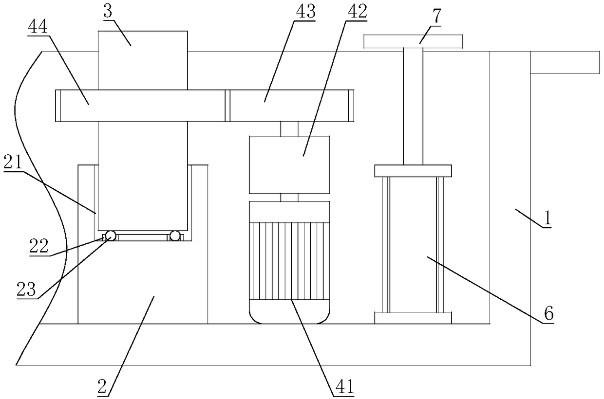
[0027] On the basis of Embodiment 1, the drive mechanism 4 includes a motor 41, the output shaft of the motor 41 is connected with a reducer 42, the motor 41 and the reducer 42 are installed on the base 1, and the output shaft of the reducer 42 is connected with a drive The gear 43 and the driving gear 43 are meshed with a driven gear 44 , and the driven gear 44 is installed on the support rod 3 .
[0028] After the motor 41 starts, the motor 41 drives the speed reducer 42 to act, the speed reducer 42 drives the driving gear 43 to rotate, and the driving gear 43 drives the driven gear 44 to rotate. When the driven gear 44 rotates, the support rod 3 is driven to rotate, and the display screen main body 5 can automatically turn to facilitate operation.
Embodiment 3
[0030] On the basis of Embodiment 1 or Embodiment 2, an annular groove 22 is fixed in the groove body 21 of the connecting seat 2 , and a plurality of balls 23 are arranged in the annular groove 22 , and the bottom of the support rod 3 overlaps the balls 23 .
[0031] When the support rod 3 rotates relative to the connecting seat 2, the ball 23 rolls in the annular groove 22, and the sliding friction on the support rod 3 becomes rolling friction, which reduces the friction force and ensures the rotation flexibility of the support rod 3.
PUM
 Abstract
Description
Claims
Application Information
 - R&D
- Intellectual Property
- Life Sciences
- Materials
- Tech Scout
- Unparalleled Data Quality
- Higher Quality Content
- 60% Fewer Hallucinations
Browse by: Latest US Patents, China's latest patents, Technical Efficacy Thesaurus, Application Domain, Technology Topic, Popular Technical Reports.
© 2025 PatSnap. All rights reserved.Legal|Privacy policy|Modern Slavery Act Transparency Statement|Sitemap|About US| Contact US: help@patsnap.com


