

Air conditioner control method and device, wire distribution equipment and air conditioner
A branching equipment, air conditioner technology, applied in the direction of mechanical equipment, etc., can solve the problems of inconvenient operation, reduced user experience, time and energy consumption, etc.
- Summary
- Abstract
- Description
- Claims
- Application Information
AI Technical Summary
Benefits of technology
Problems solved by technology
Method used
Image

Examples
no. 1 example
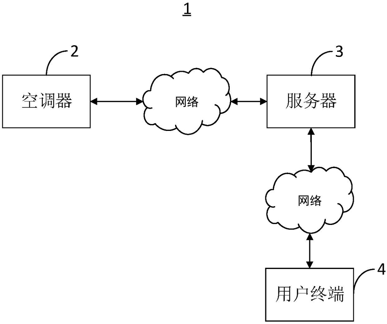
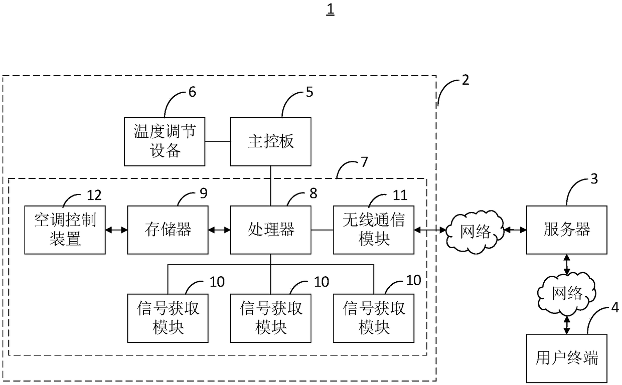
[0046] The embodiment of the present invention provides an air conditioner control system 1 for conveniently and quickly controlling the air conditioner 2 from any position within the area. see figure 1 , is a functional block diagram of the air conditioning control system 1 provided by the embodiment of the present invention. Wherein, the air conditioner control system 1 includes an air conditioner 2, a server 3 and a user terminal 4, and the air conditioner 2, the server 3 and the user terminal 4 are connected through a network communication.
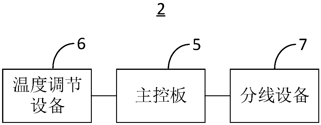
[0047] Wherein, the air conditioner 2 is used to adjust the indoor ambient temperature. see figure 2, is a functional block diagram of the air conditioner 2 provided by the embodiment of the present invention. The air conditioner 2 includes a main control board 5 , a temperature adjustment device 6 and a distribution device 7 , and the main control board 5 is electrically connected to the temperature adjustment device 6 and the di...
no. 2 example
[0079] see Figure 4 , Figure 4 It is a flow chart of an air conditioner control method provided by a preferred embodiment of the present invention. It should be noted that the air-conditioning control method provided in this embodiment is applied to the branching device 7 provided in the first embodiment, and its basic principles and technical effects are the same as those of the above-mentioned embodiments. For the parts not mentioned, reference may be made to the corresponding content in the above-mentioned embodiments. The air conditioning control method includes:
[0080] Step S401: Receive first control signals transmitted by multiple signal acquisition modules 10 .
[0081] Understandably, the first control signal is acquired and transmitted by the signal acquisition module 10 . In addition, the first control signal includes a voice control signal and an infrared light control signal.
[0082] Step S402: Analyze each first control signal to generate multiple contr...
no. 3 example
[0090] see Figure 5 , Figure 5 A functional block diagram of an air-conditioning control device 12 provided by a preferred embodiment of the present invention. It should be noted that the air conditioner control device 12 provided in this embodiment is applied to the branching device 7 provided in the first embodiment, and its basic principles and technical effects are the same as those of the above-mentioned embodiments. For a brief description, this embodiment For parts not mentioned, reference may be made to the corresponding content in the above-mentioned embodiments. The air conditioner control device 12 includes: a signal receiving unit 13 , an instruction generating unit 14 , a judging unit 15 and an instruction transmitting unit 16 .
[0091] Wherein, the signal receiving unit 13 is used for receiving the first control signals transmitted by the multiple signal acquiring modules 10 .
[0092] It can be understood that, in a preferred embodiment, the signal receivi...
PUM
 Abstract
Description
Claims
Application Information