Radio frequency switch unit and radio frequency switch circuit thereof

A radio frequency switch and circuit technology, applied in electronic switches, electrical components, pulse technology, etc., can solve problems affecting radio frequency performance, and achieve the effects of optimizing circuit structure, saving drive bias circuits, and reducing harmonic nonlinearity.

Active Publication Date: 2018-12-04
SHANGHAI HUAHONG GRACE SEMICON MFG CORP
View PDF4 Cites 5 Cited by
  • Summary
  • Abstract
  • Description
  • Claims
  • Application Information

AI Technical Summary

Problems solved by technology

This kind of RF switch circuit is simple to connect, but there is a diode (diode) voltag

Method used


Image

  • Radio frequency switch unit and radio frequency switch circuit thereof
  • Radio frequency switch unit and radio frequency switch circuit thereof
  • Radio frequency switch unit and radio frequency switch circuit thereof

Examples


Example Embodiment

[0033] The embodiments of the present invention will be described below through specific examples and in conjunction with the accompanying drawings, and those skilled in the art can easily understand other advantages and effects of the present invention from the contents disclosed in this specification. The present invention can also be implemented or applied through other different specific examples, and various details in this specification can also be modified and changed based on different viewpoints and applications without departing from the spirit of the present invention.
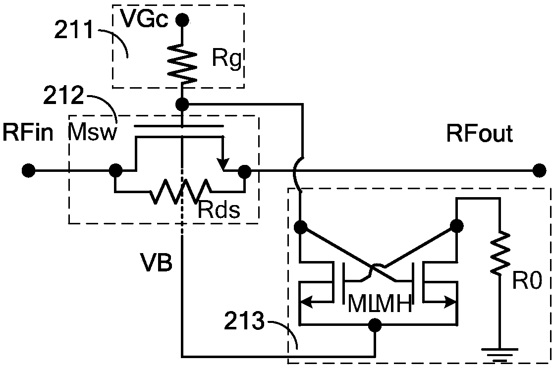
[0034] image 3 It is a schematic structural diagram of a radio frequency switch unit of the present invention. like image 3 As shown, a radio frequency switch unit of the present invention includes: a gate bias circuit 211 , a switch circuit 212 and a body region drive circuit 213 .

[0035]The gate bias circuit 211 is composed of a gate bias resistor Rg, which is used to transmit the cell gate ...


PUM


Abstract

The invention discloses a radio frequency switch unit and a radio frequency switch circuit thereof. The radio frequency switch unit comprises a grid bias circuit, a switch circuit, and a body-region driving circuit. The grid bias circuit is used for transmitting a grid control voltage VGc to a grid of a switch tube. The switch circuit includes an NMOS switching tube Msw and an access resistor Rdsand is used for transmitting or turning off a radio frequency link. The body-region driving circuit is used for converting the grid control voltage VGc of the NMOS switching tube Msw into a substratecontrol voltage VB. Therefore, a body-wide full-swing voltage-drop-free adaptive grid bias drive voltage is realized; and the body-region extra complicated driving bias circuit is saved.

Description

technical field [0001] The invention relates to the technical field of radio frequency switches, in particular to a radio frequency switch unit and a radio frequency switch circuit thereof. Background technique [0002] The body region driving method of SOI (Silicon-On-Insulator, that is, silicon on insulating substrate) switching device is very important to the breakdown voltage and process FOM ((Figure Of Merit, quality factor). A reasonable body region driving method is not only It helps to optimize the power capability of radio frequency switching, harmonics, insertion loss and isolation, and can simplify circuit design and save chip area. [0003] figure 1 It is a schematic circuit diagram of a radio frequency switch circuit biased by a single large resistance in the body region in the prior art. Such as figure 1 As shown, the radio frequency switch circuit in the prior art includes a grid voltage control module 10, a switch module 20 and a body voltage control modul...

Claims


Application Information

Patent Timeline
IPC IPC(8): H03K17/687H03K17/16
CPCH03K17/161H03K17/687
Inventor 戴若凡
Owner SHANGHAI HUAHONG GRACE SEMICON MFG CORP
Why Eureka
Try Eureka