
Design method and device for a bifocal shaped reflector antenna

A reflective surface, bifocal technology, used in antennas, electrical components and other directions, can solve difficult problems

Active Publication Date: 2020-12-29
INST OF ELECTRONICS CHINESE ACAD OF SCI
View PDF4 Cites 0 Cited by
  • Summary
  • Abstract
  • Description
  • Claims
  • Application Information

AI Technical Summary

Problems solved by technology

The reflector antenna composed of a phased array feed and a deployable mesh reflector has the characteristics of relatively simple deployment mechanism, light weight, high efficiency, and the ability to realize spatial power combining and full-power continuous scanning of the beam. At present, large-aperture lightweight deployable antennas are the mainstream in the spaceborne radar field, but it is very difficult to realize the wide-angle electronic scanning required by SAR staring imaging with phased array feed reflector antennas

Method used


Image

  • Design method and device for a bifocal shaped reflector antenna
  • Design method and device for a bifocal shaped reflector antenna
  • Design method and device for a bifocal shaped reflector antenna

Examples


Embodiment Construction

[0036] The following will clearly and completely describe the technical solutions in the embodiments of the present invention with reference to the drawings in the embodiments of the present invention.

[0037] An embodiment of the present invention provides a method for a bifocal shaped reflector antenna, such as figure 1 As shown, the method may include:

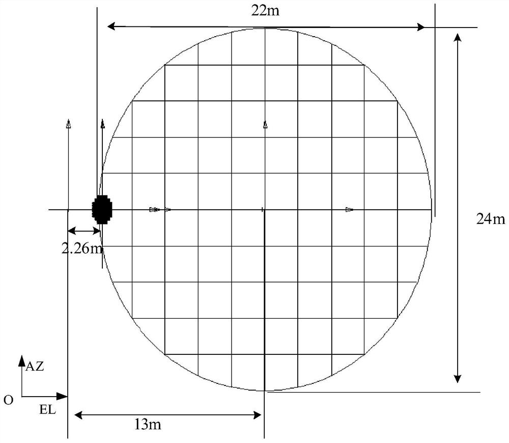
[0038] Step 101, presupposing that the shaped reflective surface is a paraboloid, and determining the curve of the azimuth tangent plane and the curve of the distance tangent plane of the shaped reflective surface.

[0039] Specifically, the method provided in the embodiment of the present invention can be used for a bifocal shaped reflector antenna, and the bifocal shaped reflector antenna at least includes: a phased array feed source and a shaped reflector.

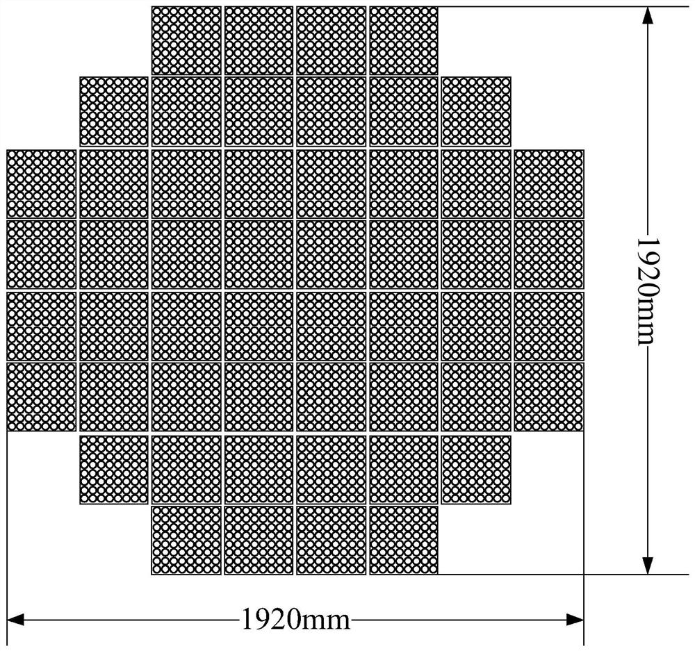
[0040] Exemplarily, the design of the two-dimensional planar active phased array feed can be as follows figure 2 As shown in the figure, the feed adopts a square...


PUM


Abstract

The embodiment of the invention discloses a method of a dual-focus shaped reflector antenna, which is used for the dual-focus shaped reflector antenna. The dual-focus shaped reflector antenna comprises a phased array feed source and a shaped reflector. The method comprises the following steps of: presetting the shaped reflector as a paraboloid, determining a curve of an azimuth direction tangent plane and a curve of a distance direction tangent plane of the shaped reflector; The curves of the azimuth tangent plane and the distance tangent plane are merged, The curved surface equation of the shaped reflector is obtained. Because the azimuth and distance of the reflector are different, the reflector antenna can realize the scanning range from azimuth + / - 5 to distance + / -3 degrees, and theantenna has a stable gain output in the scanning range. The embodiment of the invention also discloses a device of a dual-focus shaped reflector antenna, the dual-focus shaped reflector antenna and acomputer-readable storage medium.

Description

technical field [0001] The present invention relates to the multi-polarization synthetic aperture radar SAR technology in the space-borne field, and in particular to a method and device for a bifocal shaped reflector antenna, a bifocal shaped reflector antenna and a computer-readable storage medium. Background technique [0002] Geosynchronous orbit multi-polarization synthetic aperture radar (SAR, Synthetic Aperture Radar) antenna aperture area is 1000m 2 Above, it is therefore necessary to adopt lightweight deployable antenna technology. The reflector antenna composed of a phased array feed and a deployable mesh reflector has the characteristics of relatively simple deployment mechanism, light weight, high efficiency, and the ability to realize spatial power combining and full-power continuous scanning of the beam. At present, large-aperture lightweight deployable antennas are the mainstream in the spaceborne radar field, but it is very difficult to realize the wide-angle...

Claims


Application Information

Patent Timeline
Patent Type & Authority Patents(China)
IPC IPC(8): H01Q15/14H01Q15/16H01Q19/12
CPCH01Q15/141H01Q15/16H01Q19/12
Inventor 王楠吴亮欧乃铭王文涛郎宇
Owner INST OF ELECTRONICS CHINESE ACAD OF SCI
Learn More