
Confocal dual paraboloid antenna

A double paraboloid, antenna technology, applied in the direction of antenna, antenna array, specific array feeding system, etc., can solve the problem of inability to complete large-angle scanning

Active Publication Date: 2018-10-12
INST OF ELECTRONICS CHINESE ACAD OF SCI
View PDF4 Cites 2 Cited by
  • Summary
  • Abstract
  • Description
  • Claims
  • Application Information

AI Technical Summary

Problems solved by technology

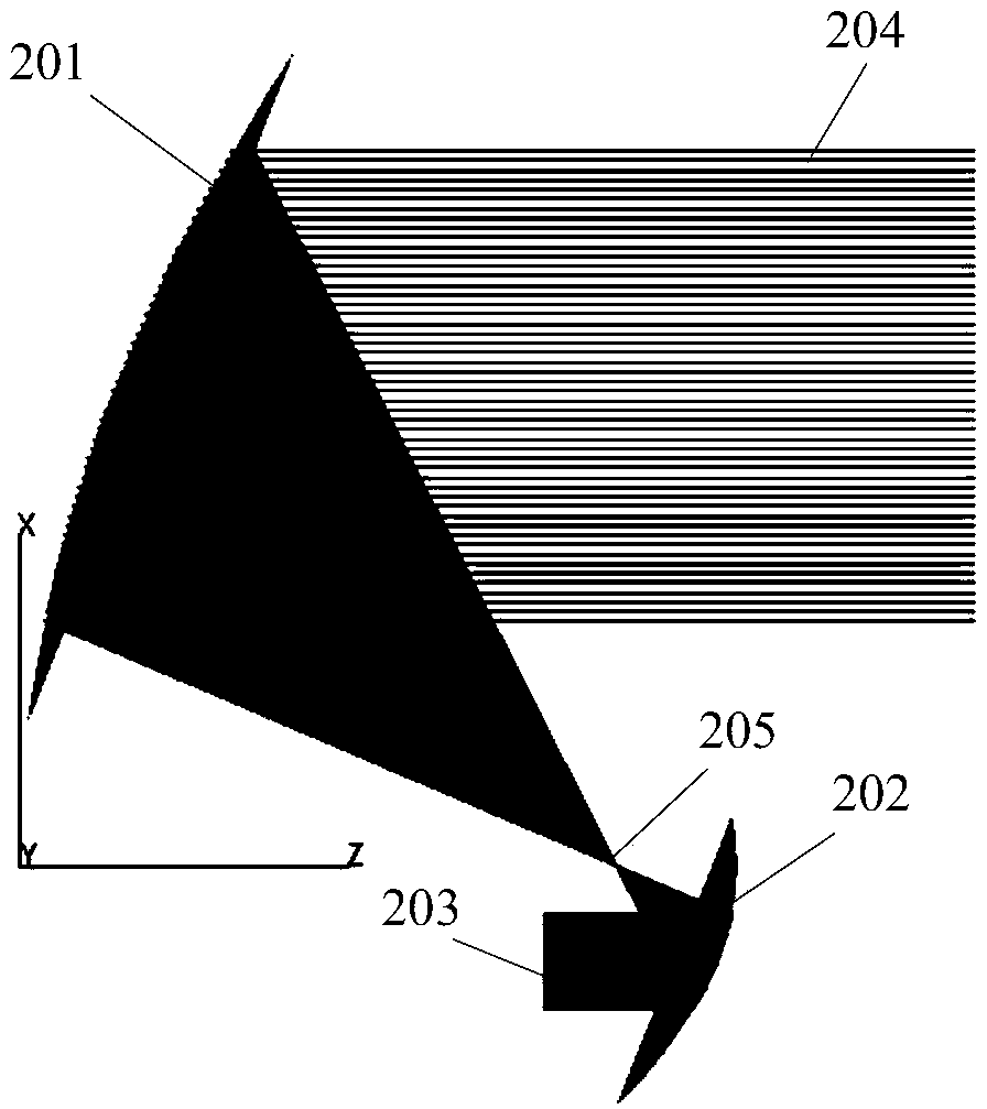
However, the secondary reflector of the Gregorian antenna is an ellipsoid, and the feed is placed on one focus of the ellipsoid, and the other focus of the ellipsoid coincides with the focus of the main reflector. While ensuring the focusing characteristics, the Gregorian antenna wide angle scan

Method used


Image

  • Confocal dual paraboloid antenna
  • Confocal dual paraboloid antenna
  • Confocal dual paraboloid antenna

Examples


Embodiment Construction

[0025] It should be understood that the specific embodiments described herein are only used to explain the present invention, but not to limit the present invention.

[0026] In the following description, use of suffixes such as 'module', 'part' or 'unit' for denoting elements is only for facilitating description of the present invention and has no specific meaning by itself. Therefore, 'module', 'part' or 'unit' may be used in combination.

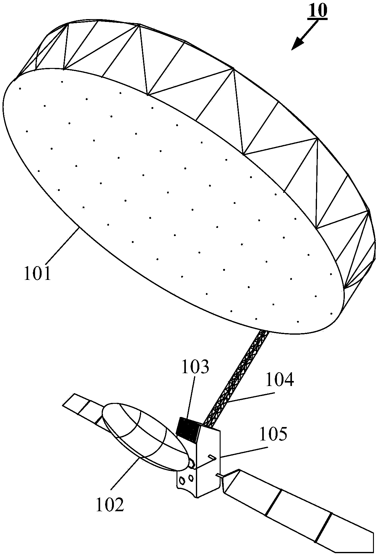
[0027] An embodiment of the present invention provides a confocal dual parabolic antenna, figure 1 It is a schematic diagram of the three-dimensional structure of the confocal dual-parabolic antenna described in the embodiment of the present invention, such as figure 1 As shown, the confocal dual parabolic antenna 10 includes a main reflector 101, a secondary reflector 102 and a feed 103, wherein:

[0028] The main reflective surface 101 and the secondary reflective surface 102 are oppositely arranged and confocal; wherein, the primary ...


PUM


Abstract

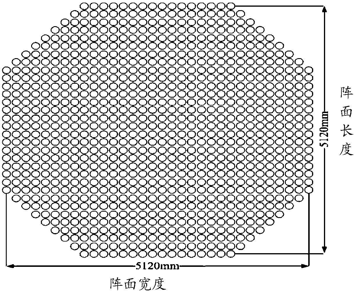
An embodiment of the invention provides a confocal dual paraboloid antenna. The confocal dual paraboloid antenna at least comprises a main reflective surface, a secondary reflective surface and a feedsource, wherein the main reflective surface and the secondary reflective surface are arranged oppositely and confocal, wherein the main reflective surface and the secondary reflective surface are both paraboloid; the main reflective surface and the secondary reflective surface have the same focal point; and the feed source is an active phase control array feed source capable of performing two-dimensional electronic scanning, and is arranged at the front end of the secondary reflective surface.

Description

technical field [0001] The invention relates to antenna technology, in particular to a confocal double parabolic antenna. Background technique [0002] Confocal Dual Paraboloid Antenna (CDPA), also known as Confocal Gregorian Antenna (CGA), was proposed by foreign scholars in the 1970s. The difference between the confocal double-parabolic antenna and any other dual-reflector antenna system is that this antenna does not focus on the plane wave, but compresses the large-aperture plane wave at the front end of the main surface into a small-aperture plane wave at the front end of the secondary surface, and then transmits it at the front end of the secondary surface. Place a planar array antenna corresponding to the plane wave aperture as the feed source. When the planar array feed source is radiated in the same phase, the small-aperture plane wave wavefront generated by it will be amplified into a large-aperture plane wave wavefront by the double paraboloid system, thereby impro...

Claims


Application Information

Patent Timeline
Patent Type & Authority Applications(China)
IPC IPC(8): H01Q19/19H01Q21/00
CPCH01Q19/19H01Q21/0006
Inventor 王楠欧乃铭吴亮王文涛郎宇
Owner INST OF ELECTRONICS CHINESE ACAD OF SCI
Learn More