
Cylinder body oil inlet double-action multi-stage hydraulic cylinder

A double-acting, hydraulic cylinder technology, applied in the field of multi-stage hydraulic cylinders, can solve problems such as easy wear of sealing rings, failure of double-acting multi-stage hydraulic cylinders, internal leakage of hydraulic cylinders, etc., and achieve the effect of reducing interaction force

Pending Publication Date: 2018-12-14
NO 719 RES INST CHINA SHIPBUILDING IND
View PDF0 Cites 3 Cited by
  • Summary
  • Abstract
  • Description
  • Claims
  • Application Information

AI Technical Summary

Problems solved by technology

[0004] In view of the defects existing in the prior art, the object of the present invention is to provide a double-acting multi-stage hydraulic cylinder of the present invention, which can effectively solve the problem that the double-acting multi-stage hydraulic cylinder cannot work normally under alternating loads. problems, as well as the problem that the sealing ring is easy to wear caused by the radial hole of the traditional multi-stage hydraulic cylinder, avoiding the internal leakage of the hydraulic cylinder, and the problem that the hydraulic cylinder is easy to overpressure caused by the pressure regulating valve such as the ordinary stroke valve, Ensure that each level of hydraulic cylinder will not appear overpressure

Method used


Image

  • Cylinder body oil inlet double-action multi-stage hydraulic cylinder
  • Cylinder body oil inlet double-action multi-stage hydraulic cylinder
  • Cylinder body oil inlet double-action multi-stage hydraulic cylinder

Examples


Embodiment Construction

[0069] The present invention will be described in further detail below in conjunction with the accompanying drawings and embodiments.

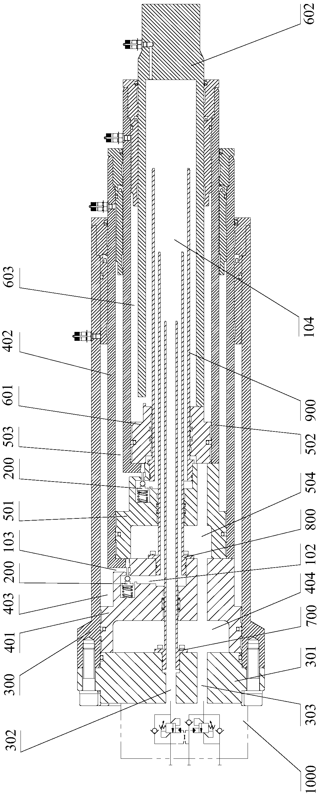
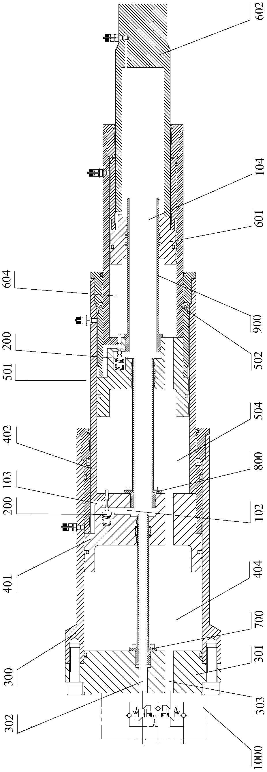
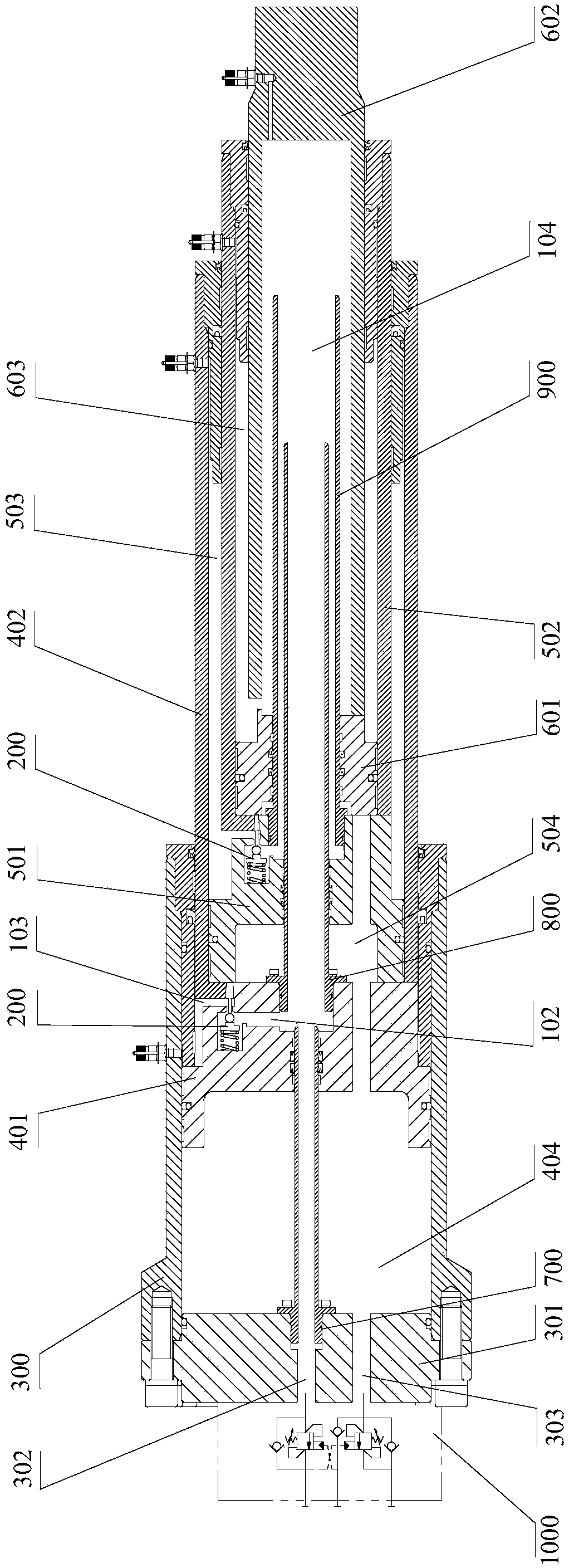
[0070] see figure 1 As shown, the embodiment of the present invention provides a cylinder block oil-inlet double-acting multi-stage hydraulic cylinder, which includes a cylinder block 300, at least two stages of piston rod assemblies, a plurality of one-way valve assemblies and a balance valve group.

[0071] Wherein, the cylinder block 300 has a cylinder head 301 fixed on its end, and the cylinder head 301 includes a first cylinder head hole 302 and a second cylinder head hole 303 arranged along the axial direction of the cylinder body 300, and the first cylinder head hole 302 and the second cylinder head hole 303 are arranged at intervals along the radial direction of the cylinder block 300 .

[0072] There are at least two stages of piston rod assemblies that are sheathed step by step, which are arranged in the cylinder body 300. Each stag...


PUM


Abstract

The invention discloses a cylinder body oil inlet double-action multi-stage hydraulic cylinder, and relates to the field of hydraulic cylinders. The cylinder body oil inlet double-action multi-stage hydraulic cylinder comprises a cylinder body, at least two stages of piston rod assemblies arranged in the cylinder body in a sleeving mode stage by stage, multiple one-way valve assemblies, an ejection rod device and a balancing valve assembly; each piston rod assembly comprises a piston and a piston rod fixed to the piston; each one-way valve assembly comprises an in-cylinder one-way valve used for controlling rod cavities of the corresponding adjacent two stages of piston rod assemblies to communicate with each other or be intercepted; the ejection rod device is used for driving the in-cylinder one-way valves to be opened or closed, when the pistons in every two adjacent stages of the piston rod assemblies are separated in the stretching or retracting process, the ejection rod device isself-locked; and when the pistons in every two adjacent stages of the piston rod assemblies make contact with each other in the stretching or retracting process, the ejection rod device drives the in-cylinder one-way valves to be opened; and the balancing valve assembly is fixed to the cylinder body. According to the cylinder body oil inlet double-action multi-stage hydraulic cylinder, the problemthat a sealing ring is prone to being worn due to the fact that a traditional multi-stage hydraulic cylinder adopts radial holes can be solved, internal leakage of the hydraulic cylinder is avoided,and it is guaranteed that each stage of a hydraulic cylinder body can not generate the overpressure phenomenon.

Description

technical field [0001] The invention relates to the field of multi-stage hydraulic cylinders, in particular to a double-acting multi-stage hydraulic cylinder with oil feeding into a cylinder body. Background technique [0002] On hydraulic engineering machinery or large hydraulic equipment, due to the limitation of installation space and the complex and changeable load, it is usually necessary to use multi-stage hydraulic cylinders and work under alternating loads. Ordinary multi-stage hydraulic cylinders generally adopt a structure with radial holes in the cylinder barrel in order to ensure the expansion and contraction sequence of the hydraulic cylinder. This structure is widely used in construction machinery with low requirements. Since the diameter of the radial hole of the cylinder must be smaller than the width of the piston seal ring, usually not less than 2mm, in order to ensure the flow area, it is necessary to distribute a large number evenly along the radial direc...

Claims


Application Information

Patent Timeline
Patent Type & Authority Applications(China)
IPC IPC(8): F15B15/14F15B15/20
CPCF15B15/1447F15B15/1457F15B15/20
Inventor 喻卫宁唐辉邢晓文徐锋童骏肖涛吴鲲谭颖
Owner NO 719 RES INST CHINA SHIPBUILDING IND
Learn More