
An automatic sandblasting equipment

A kind of sandblasting equipment and automatic technology, which is applied in metal processing equipment, abrasive jetting machine tools, used abrasive processing devices, etc., can solve the problems of low production efficiency, waste of abrasive particles, large damage to edges and corners of metal blocks, etc. problems, to achieve the effect of facilitating recycling, improving work efficiency and preventing pollution

Active Publication Date: 2019-12-13
安徽省玛蒂瑞尔化学有限公司
View PDF5 Cites 0 Cited by
  • Summary
  • Abstract
  • Description
  • Claims
  • Application Information

AI Technical Summary

Problems solved by technology

[0002] The existing sandblasting equipment is generally semi-automatic production. During the production process, people hold the sandblasting gun and perform manual sandblasting on the sandblasting gun. The manual sandblasting process is uneven, and the edges and corners of the metal block are greatly damaged. , high labor intensity and low production efficiency; moreover, the sand particles of a general sandblasting machine are treated as waste after only one blasting, and the utilization rate of the sand particles is low.
[0003] In addition, the existing sandblasting machines usually process the workpiece in an open or semi-open environment, and the sand particles will fly around after hitting the workpiece during the sandblasting process, which not only endangers the health of the operator, but also cause serious pollution to the environment

Method used


Image

  • An automatic sandblasting equipment
  • An automatic sandblasting equipment
  • An automatic sandblasting equipment

Examples


Embodiment Construction

[0036] The following will clearly and completely describe the technical solutions in the embodiments of the present invention with reference to the accompanying drawings in the embodiments of the present invention. Obviously, the described embodiments are only some, not all, embodiments of the present invention. Based on the embodiments of the present invention, all other embodiments obtained by persons of ordinary skill in the art without creative efforts fall within the protection scope of the present invention.

[0037] In describing the present invention, it is to be understood that the terms "opening", "upper", "lower", "thickness", "top", "middle", "length", "inner", "surrounding" etc. Indicating orientation or positional relationship is only for the convenience of describing the present invention and simplifying the description, and does not indicate or imply that the components or elements referred to must have a specific orientation, be constructed and operated in a sp...


PUM


Abstract

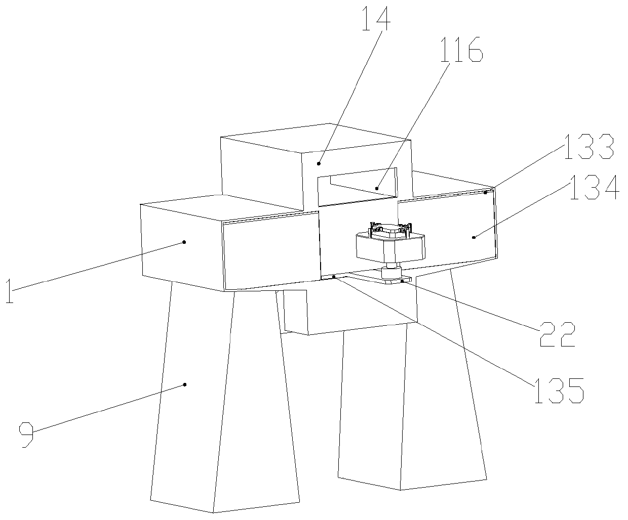
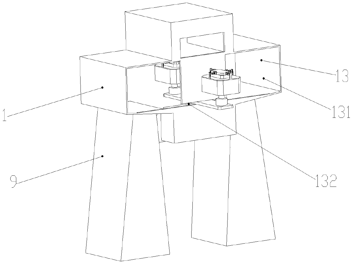
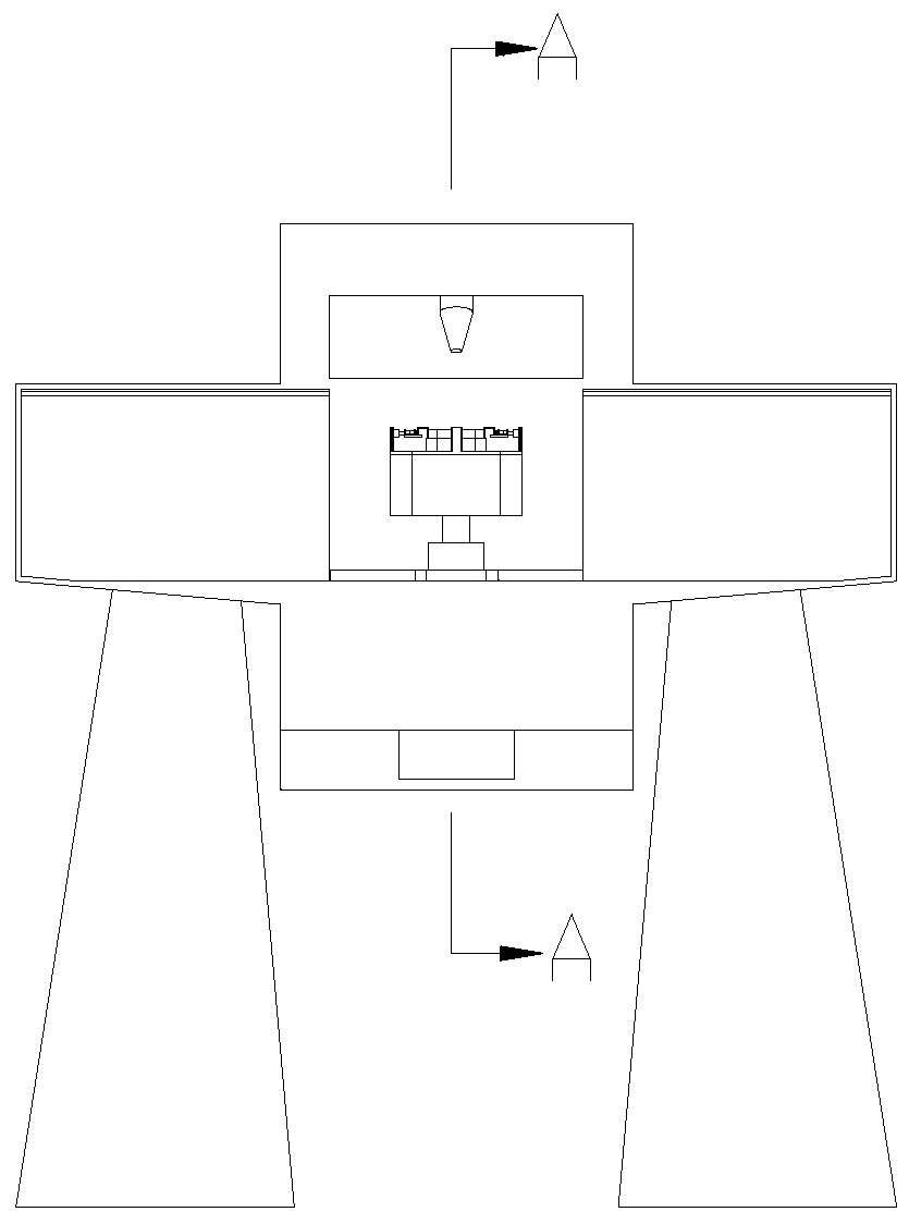
The invention discloses an automatic sand blasting device. The automatic sand blasting device comprises a shell. The interior of the shell is divided into a sand blasting bin, a containing bin and aninlet and outlet bin. A sand blasting gun is arranged at the upper end of the sand blasting bin. A first motor is arranged at the bottom end of the containing bin. The output end of the first motor isprovided with a first rotating shaft. A supporting plate is arranged on the first rotating shaft. The supporting plate is provided with second motors. The output ends of the second motors are provided with second rotating shafts. A ring-shaped shell is arranged at one end of each second rotating shaft, and rotating units are arranged at the upper end of each ring-shaped shell. A clamping unit isarranged on each rotating unit. A reset spring is arranged at the upper end of the bottom of each ring-shaped shell, and a containing plate is arranged at the upper end of each reset spring. Metal blocks needing to be subjected to sand blasting are placed in the containing plates; the first motor is started to drive the containing plates to rotate to the position below the sand blasting gun; the sand blasting gun conducts sand blasting on the metal blocks; in the sand blasting process, when sand blasting of the upper surfaces of the metal blocks is completed, air cylinders are started so thatthe metal blocks can be clamped by clamping blocks; and third motors are started, the third motors drive the metal blocks to overturn, and sand blasting is conducted on the other faces of the metal blocks.

Description

technical field [0001] The invention relates to a sandblasting equipment, in particular to an automatic sandblasting equipment. Background technique [0002] The existing sandblasting equipment is generally semi-automatic production. During the production process, people hold the sandblasting gun and perform manual sandblasting on the sandblasting gun. The manual sandblasting process is uneven, and the edges and corners of the metal block are greatly damaged. , high labor intensity and low production efficiency; moreover, the sand particles of a general sandblasting machine are treated as waste after only one blasting, and the utilization rate of the sand particles is low. . [0003] In addition, the existing sandblasting machines usually process the workpiece in an open or semi-open environment, and the sand particles will fly around after hitting the workpiece during the sandblasting process, which not only endangers the health of the operator, but also Great pollution t...

Claims


Application Information

Patent Timeline
Patent Type & Authority Patents(China)
IPC IPC(8): B24C3/02B24C9/00
CPCB24C3/02B24C9/006
Inventor 张文涛张国锐
Owner 安徽省玛蒂瑞尔化学有限公司
Learn More