
Spring-reset plastic molding mould for pushing and retracting stripping by forced deformation of support group

A technology of spring return and plastic molding, which is applied in the field of plastic molds, can solve the problems of scratching damage of finished products, difficulty in ejecting, and increase the probability of damage to finished products, so as to prevent the increase of contact area and prevent the effect of difficult material removal

Active Publication Date: 2018-12-18
广州市旭匠精密科技有限公司
View PDF4 Cites 2 Cited by
  • Summary
  • Abstract
  • Description
  • Claims
  • Application Information

AI Technical Summary

Problems solved by technology

[0002] The current molding die device usually uses two rods to push the gears and rollers on one side with racks of different heights to engage with each other, so that the rods are pushed out of different heights to achieve the release slope, so as to complete Plastic parts come off the film, but in this way it is easy to cause:
[0003] During the demoulding work, the plastic parts attached to the mold core are simultaneously pushed out through two rods of different heights, which will turn the finished product out and drop it, increasing the probability of damage to the finished product, and at the same time, it is easy to make the plastic part on the top When moving, the finished product is scratched due to the viscosity of the plastic parts. At the same time, with the gear meshing activities, the internal gears will age after a long time of work, which makes the ejection difficult and increases the labor intensity of the staff.

Method used


Image

  • Spring-reset plastic molding mould for pushing and retracting stripping by forced deformation of support group
  • Spring-reset plastic molding mould for pushing and retracting stripping by forced deformation of support group
  • Spring-reset plastic molding mould for pushing and retracting stripping by forced deformation of support group

Examples


Embodiment

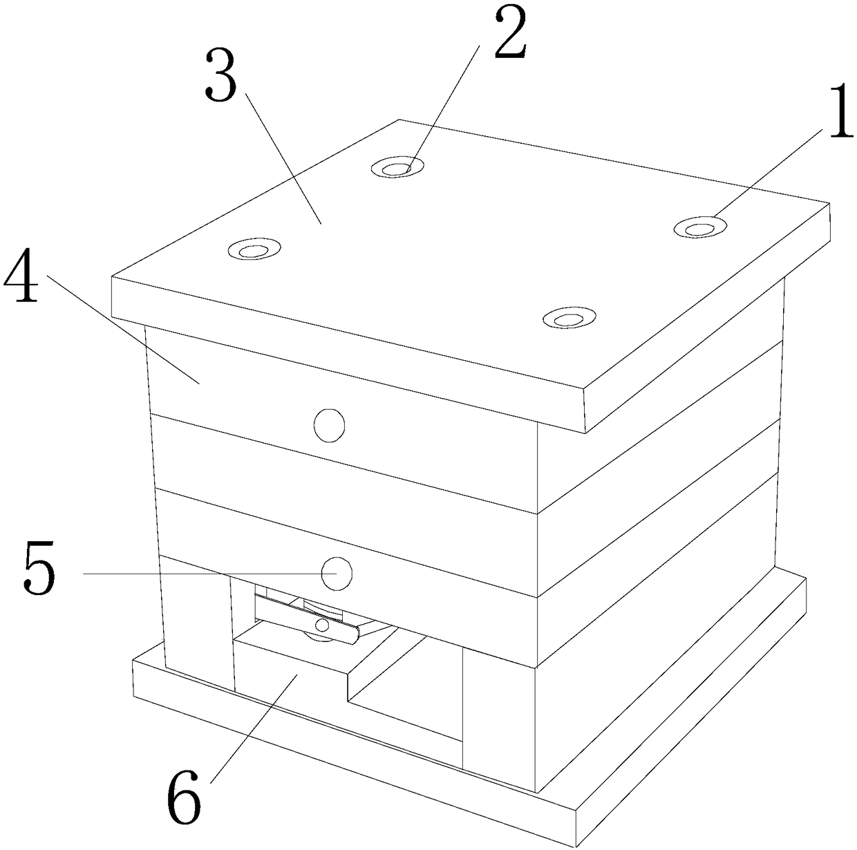
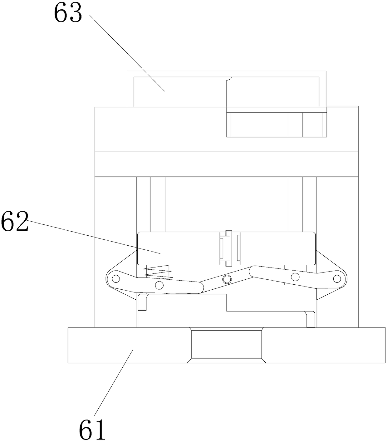
[0025] see figure 1 , the present invention provides a spring-return plastic molding mold that is deformed by force, shrinkage and stripping of the support group. The material device 6, the forming and stripping device 6 is located at the lower side end surface of the fixed mold base 4, and the two are connected, and the fixed mold base 4 is arranged on the lower side end surface of the fixed template 3, and the two are flexibly connected. 5 is embedded in the fixed mold base 4 and is an integrated structure with the fixed mold base 4, the guide post hole 1 is located on the upper surface of the fixed template 3 and is embedded in the fixed template 3 while being movably connected with the fixed template 3. The inside of the guide post 2 embedded in the guide post hole 2 adopts a clearance fit, and the water inlet hole 5 is provided with a bayonet-shaped back-shaped special-shaped structure inside, through which the bayonet-shaped back-shaped special-shaped structure can pass...


PUM


Abstract

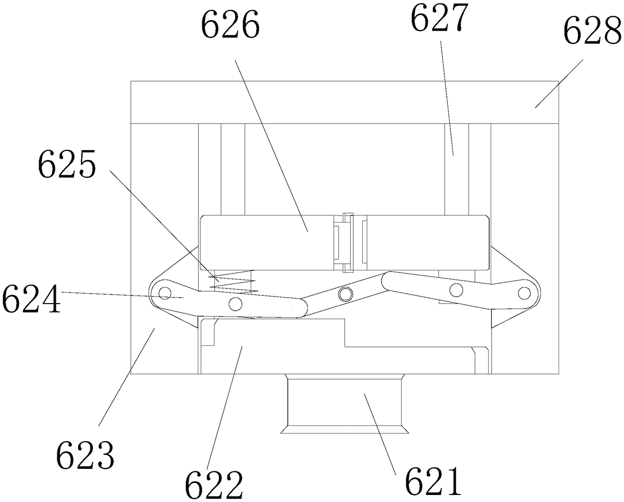
The invention discloses a spring-reset plastic molding mould for pushing and retracting stripping by forced deformation of a support group. The spring-reset plastic forming mould comprises a guide column hole, a guide column, a fixed die plate, a fixed die holder, a water inlet hole and a molding stripping device, wherein the molding stripping device is positioned on the end face of the lower sideof the fixed die holder and is in fit connection with the fixed die seat. A special-shaped block in the inner part is pushed upwards by a movable column at the lower part, and a regulating bracket onthe upper part moves to deform, so that one side of a pushing column in the inner part is pushed out slightly, the other side of the pushing column is retracted into and matched with the inner part of an unloading bracket, and therefore demoulding gradient is formed. Forced pushing by a rod body is not adopted, so that unloading is more stable, and the safety of finished products is ensured. A permanent magnet repelling a magnetic block is arranged in the inner part of a sliding block and is matched with the magnetic block, and the sliding block is matched with a sliding groove in a sliding mode, so that a block body can move stably along an arc-shaped column, the pushing column rising by forced pushing can be more smooth and stable, and difficult push-out due to aging cannot occur.

Description

technical field [0001] The invention relates to the field of plastic moulds, in particular to a spring-returning plastic molding mould, which is deformed and ejected by a support group under force. Background technique [0002] The current molding die device usually uses two rods to push the gears and rollers on one side with racks of different heights to engage with each other, so that the rods are pushed out of different heights to achieve the release slope, so as to complete Plastic parts come off the film, but in this way it is easy to cause: [0003] During the demoulding work, the plastic parts attached to the mold core are simultaneously pushed out through two rods of different heights, which will turn the finished product out and drop it, increasing the probability of damage to the finished product, and at the same time, it is easy to make the plastic part on the top When moving, the finished product is scratched due to the viscosity of the plastic parts. At the sam...

Claims


Application Information

Patent Timeline
IPC IPC(8): B29C45/26B29C45/40
CPCB29C45/26B29C45/4005
Inventor 黄佳彬
Owner 广州市旭匠精密科技有限公司
Learn More