Caster connector with variable height

A connector and variable technology, applied in the lubrication of casters, wheels, engines, etc., can solve the problems of poor anti-vibration effect of casters and non-adjustable height of casters, and achieve good anti-vibration effect

Active Publication Date: 2018-12-18
ZHEJIANG HOUDAR INTELIGENT TECH CO LTD
View PDF6 Cites 0 Cited by
  • Summary
  • Abstract
  • Description
  • Claims
  • Application Information

AI Technical Summary

Problems solved by technology

[0003] The first object of the present invention is to provide a height-variable caster connector to solve the problem that the height of existing casters cannot be adjusted
[0004] The second object of the present invention is to provide a variable-height caster connector with good anti-vibration effect, which is used to solve the problem of poor anti-vibration effect of existing casters

Method used


Image

  • Caster connector with variable height
  • Caster connector with variable height
  • Caster connector with variable height

Examples


Embodiment 1

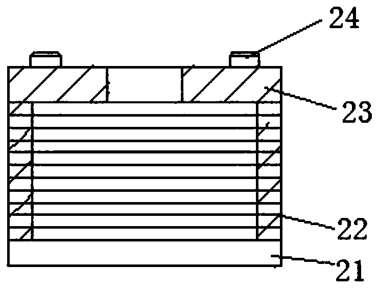
[0023] Embodiment one, see figure 1 , a height-variable caster connector, including a base plate 21, a number of height-adjusting backing plates 22 padded on the bottom plate, and a pressure plate 23 located on the uppermost backing plate. Pressing plate is connected together with base plate by the connecting screw rod 24 that passes pressing plate and height adjustment backing plate simultaneously. The connecting bolts are directly threaded on the base plate. The rubber wheels are connected to the bottom plate during use. The object supported by the casters is attached to the pressure plate.

Embodiment 2

[0024] Embodiment two, the difference with embodiment one is:

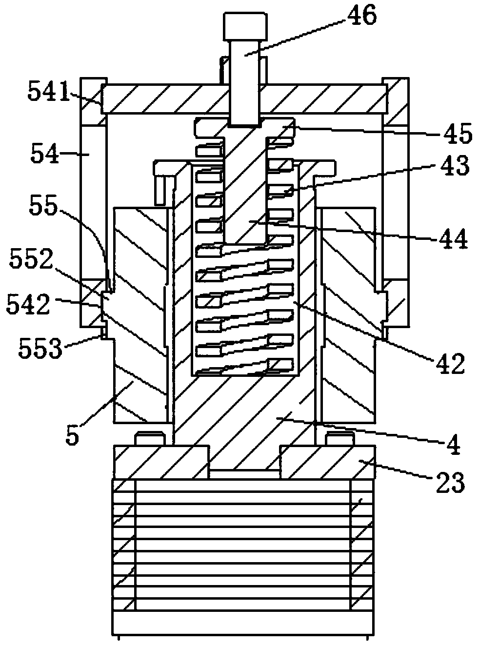
[0025] see figure 2 , the pressing plate is provided with a central column 4. A connecting sleeve 5 is sheathed on the central column. The connecting sleeve is provided with two connecting plates 54 evenly distributed along the circumference of the connecting sleeve. The connection sleeve 5 is provided with a connection protrusion ring 55 extending along the circumference of the connection sleeve. Threaded connection holes extending along the up and down directions are arranged on the connecting protruding ring. The objects supported by the casters are connected in the threaded connection holes by bolts to realize the connection with the present invention. A straight section 552 is provided at both radial ends of the connecting convex ring. A limiting notch 553 extending along the horizontal direction is provided on the lower edge of the straight section. The upper end of the connecting plate is provided wi...

Embodiment 3

[0027] Embodiment three, the difference with embodiment two is:

[0028] Adjacent height adjustment pads are connected together by Belleville springs.

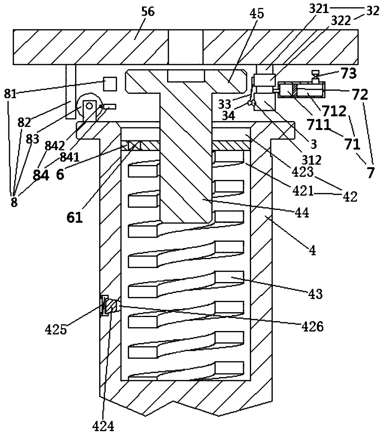
[0029] see image 3 , Figure 4 , Figure 5 and Figure 6 , the positioning rod 44 is fixedly connected with the compression plate 6 which is slidingly and sealingly connected in the spring installation hole 42 . The compression plate isolates a sealed fat storage chamber 421 and a spare fat storage bowl 423 above the fat storage chamber in the spring installation hole. The damping spring 43 is located in the sealed grease storage chamber and supported on the lower surface of the compression plate. The side wall of the spring mounting hole is provided with an oil outlet window 426 penetrating through the sealed grease storage chamber. The oil outlet window is provided with a sealing plug 424 and a window closing spring 425 that drives the sealing plug to move toward the sealed grease storage chamber to seal the oil outle...


PUM


Abstract

The invention relates to a caster connector with variable height, comprising a base plate, a plurality of height adjusting pads padded on the base plate and a pressing plate positioned on the uppermost pad plate, the pressing plate being connected with the base plate by connecting bolts passing through the pressing plate and the height adjusting pads simultaneously. The caster connector comprisesa base plate, a plurality of height adjusting pads and a pressing plate positioned on the uppermost pad plate. A first object of the present invention is to provide a highly variable caster connectorfor solving the problem that the existing rubber wheel height cannot be adjusted.

Description

technical field [0001] The invention relates to equipment in the technical field of traditional Chinese medicine production, in particular to a height-variable caster connector. Background technique [0002] The original traditional Chinese medicines are basically decocted manually. In order to realize the automatic production of traditional Chinese medicines, those skilled in the art have designed automatic production equipment for traditional Chinese medicines. For the convenience of moving equipment, caster connectors are usually provided on the equipment. The existing caster connector has the following disadvantages: the height cannot be adjusted; the anti-vibration effect is poor. Contents of the invention [0003] The first object of the present invention is to provide a height-variable caster connector, which is used to solve the problem that the height of existing casters cannot be adjusted. [0004] The second object of the present invention is to provide a vari...

Claims


Application Information

Patent Timeline
IPC IPC(8): B60B33/00B60B33/04F16N11/00F16N23/00
CPCB60B33/0002B60B33/045F16N11/00F16N23/00
Inventor 蔡永潮
Owner ZHEJIANG HOUDAR INTELIGENT TECH CO LTD
Why Eureka
Try Eureka