
Slow vibration caster assembly

A caster and assembly technology, applied in the direction of casters, wheels, vehicle parts, etc., can solve the problems of poor anti-vibration effect of casters, and achieve the effect of good anti-vibration effect and small wear

Active Publication Date: 2020-02-18
ZHEJIANG HOUDAR INTELIGENT TECH CO LTD
View PDF6 Cites 0 Cited by
  • Summary
  • Abstract
  • Description
  • Claims
  • Application Information

AI Technical Summary

Problems solved by technology

[0003] The invention provides a vibration-slowing type caster assembly, which is used to solve the problem of poor anti-vibration effect of existing casters

Method used


Image

  • Slow vibration caster assembly
  • Slow vibration caster assembly
  • Slow vibration caster assembly

Examples


Embodiment 1

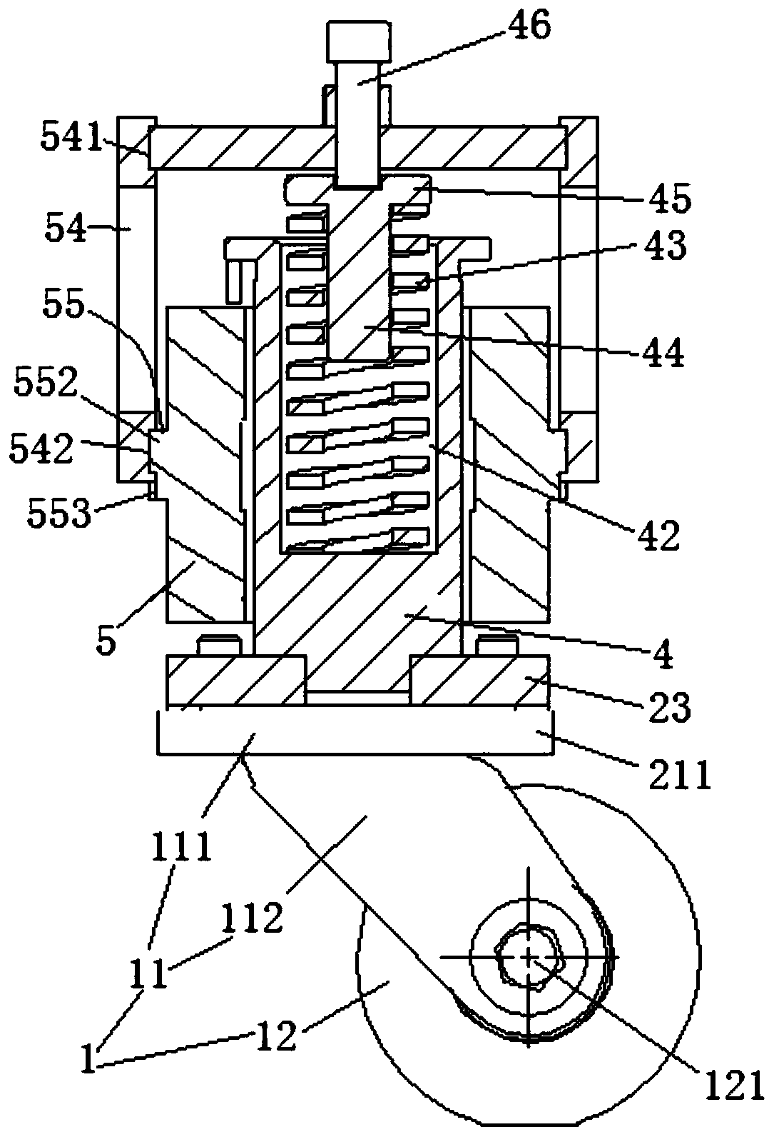
[0020] Embodiment one, see figure 1 with figure 2 , a vibration-slowing caster assembly, including a caster 1 and a caster connection structure.

[0021] The caster 1 includes a wheel frame 11 and a disc-shaped plastic roller 12 . The wheel frame 11 includes a horizontal connecting rod 111 and two vertical connecting rods 112 whose upper ends are connected together with the horizontal connecting rod. The disc-shaped plastic roller 12 is located between the two vertical and horizontal connecting rods and is connected together with the two vertical connecting rods by the axle 121 .

[0022] The caster connection structure includes a caster connection seat 23 . The transverse connecting rod 111 of the rubber wheel is connected to the below of the caster connecting seat through the connecting screw rod 24 . A central post 4 is provided on the caster connection seat. A connecting sleeve 5 is sheathed on the central column. The connecting sleeve is also provided with two conn...

Embodiment 2

[0024] Embodiment two, the difference with embodiment one is:

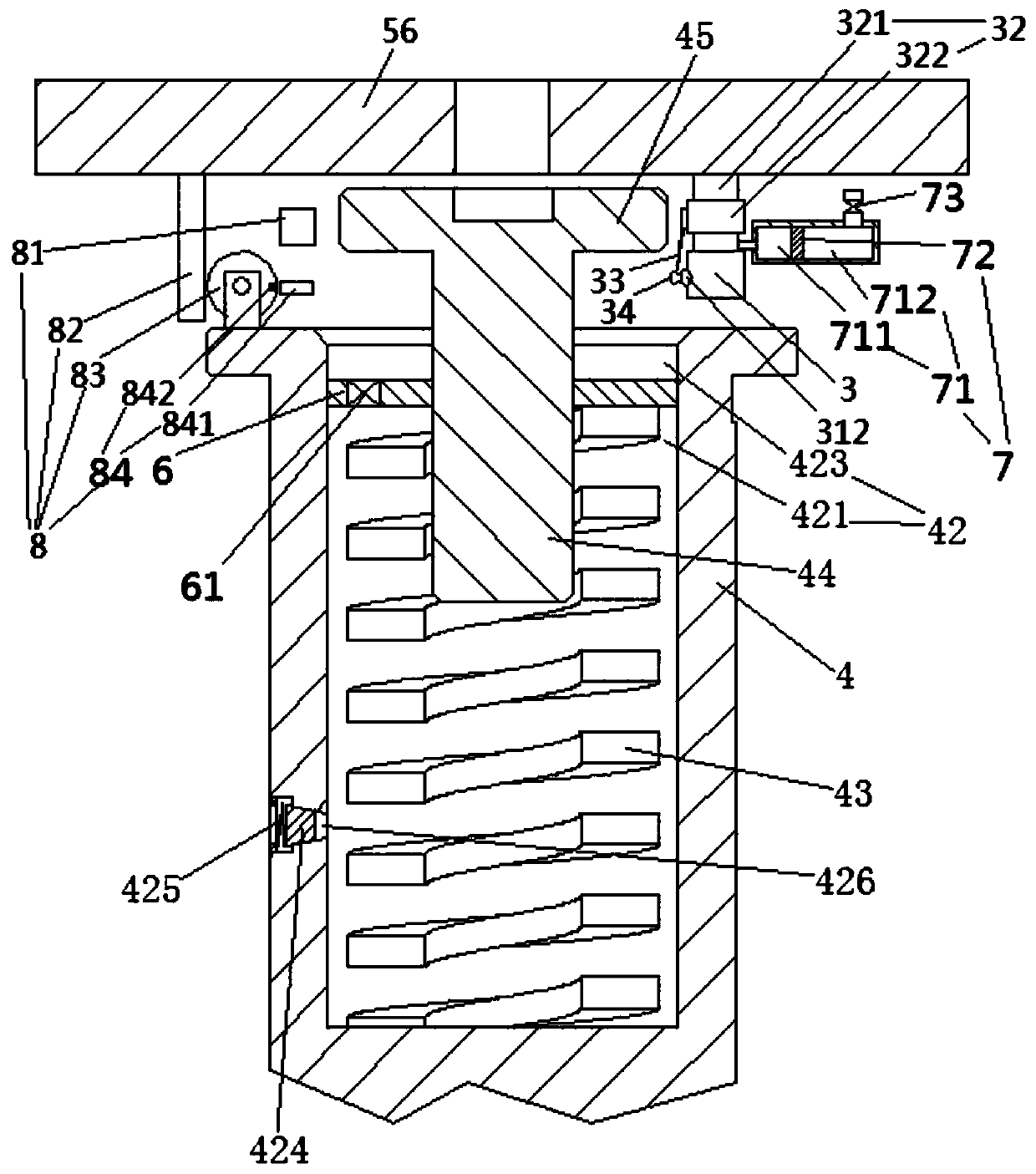
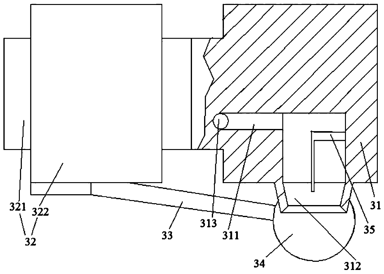
[0025] see image 3 , Figure 4 with Figure 5 The positioning rod 44 is fixedly connected with the compression plate 6 which is slidingly and sealingly connected in the spring installation hole 42 . The compression plate isolates a sealed fat storage chamber 421 and a spare fat storage bowl 423 above the fat storage chamber in the spring installation hole. The damping spring 43 is located in the sealed grease storage chamber and supported on the lower surface of the compression plate. The side wall of the spring mounting hole is provided with an oil outlet window 426 penetrating through the sealed grease storage chamber. The oil outlet window is provided with a sealing plug 424 and a window closing spring 425 that drives the sealing plug to move toward the sealed grease storage chamber to seal the oil outlet window. The compression plate is provided with a one-way valve 61 on the compression plate that opens...


PUM


Abstract

The invention relates to a vibration damping type trundle assembly. The vibration damping type trundle assembly comprises a trundle body and a trundle connecting structure. The trundle connecting structure comprises a trundle connecting base; a central column is arranged on the trundle connecting base; the central column is sleeved with a connecting sleeve; the connecting sleeve is provided with acrosspiece located above the center column, a spring installation hole is formed in the upper end face of the center column, a damping spring stretching out and drawing back in the vertical directionis arranged in the spring installation hole, the upper end of the damping spring is supported on the crosspiece, and the trundles are connected to the lower portion of the trundle connecting base. The invention provides a vibration damping type trundle assembly which is used for solving the problem that an existing trundle is poor in anti-vibration effect.

Description

technical field [0001] The invention relates to equipment in the technical field of traditional Chinese medicine production, in particular to a vibration-slowing type caster assembly. Background technique [0002] The original traditional Chinese medicines are basically decocted manually. In order to realize the automatic production of traditional Chinese medicines, those skilled in the art have designed automatic production equipment for traditional Chinese medicines. For the convenience of moving equipment, caster assemblies are usually provided on the equipment. The existing caster assembly has the following disadvantages: the anti-vibration effect is poor. Contents of the invention [0003] The invention provides a vibration-slowing caster assembly, which is used to solve the problem of poor anti-vibration effect of the existing casters. [0004] The above technical problems are solved by the following technical solutions: a vibration-slowing type caster assembly, in...

Claims


Application Information

Patent Timeline
IPC IPC(8): B60B33/04B60B33/00F16N11/00
CPCB60B33/0028B60B33/045F16N11/00
Inventor 蔡永潮
Owner ZHEJIANG HOUDAR INTELIGENT TECH CO LTD
Learn More