A kind of construction nail puller

A technology for nail pullers and iron nails, applied in the direction of nail pullers, manufacturing tools, etc., can solve problems such as nail bending, claw hammer damage, etc., achieve the effect of stabilizing and avoiding jamming, and improving work efficiency

Active Publication Date: 2021-11-05
安徽金贺财建筑工程有限公司
View PDF0 Cites 0 Cited by
  • Summary
  • Abstract
  • Description
  • Claims
  • Application Information

AI Technical Summary

Problems solved by technology

[0003] In order to overcome the shortcomings that people usually use a claw hammer to pull out the nails, because there is no point of leverage, the nails are easily bent when pulling out, which will affect subsequent use, and if the operation is not done properly, it is easy to be injured by the claw hammer, the technical problem to be solved : Provide a construction nail puller that can pull out nails more conveniently to avoid bending, and is not easy to be damaged

Method used


Image

  • A kind of construction nail puller
  • A kind of construction nail puller

Examples


Embodiment 1

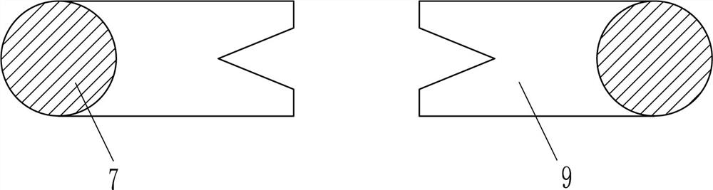
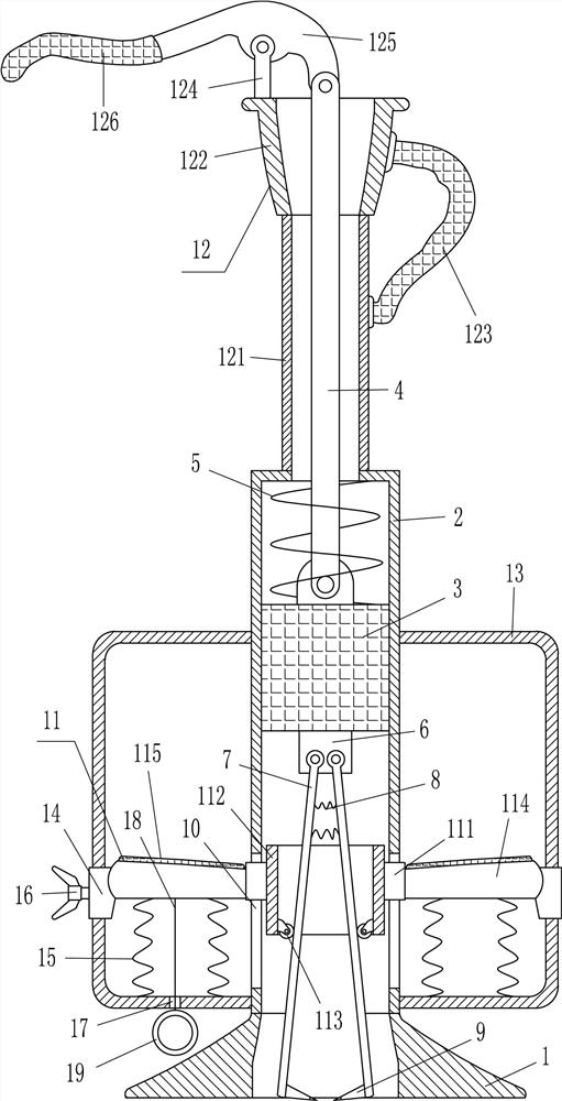
[0015] A kind of construction nail puller, such as Figure 1-2 As shown, it includes a base 1, a housing 2, a movable block 3, a pull rod 4, a first spring 5, a connecting block 6, a swing rod 7, a second spring 8, a card plate 9 and a pushing device 11, and the top of the base 1 is fixed There is a shell 2, the base 1 is connected to the shell 2 by means of bolts, the shell 2 is provided with a movable block 3, the top of the movable block 3 is connected with a pull rod 4 in a rotating manner, and the top of the pull rod 4 runs through the middle of the top of the shell 2 A first spring 5 is wound between the top of the movable block 3 and the inner top of the housing 2, and a connecting block 6 is fixedly connected to the middle of the bottom of the movable block 3. The left and right sides of the front side are rotatably connected with swing rods 7, and the lower parts of the inner sides of the left and right swing rods 7 are fixedly connected with clamps 9 for pulling up n...

Embodiment 2

[0017] A kind of construction nail puller, such as Figure 1-2 As shown, it includes a base 1, a housing 2, a movable block 3, a pull rod 4, a first spring 5, a connecting block 6, a swing rod 7, a second spring 8, a card plate 9 and a pushing device 11, and the top of the base 1 is fixed There is a housing 2, and the housing 2 is provided with a movable block 3, and the middle of the top of the movable block 3 is connected with a pull rod 4 in a rotating manner. The first spring 5 is wound around, the connecting block 6 is fixedly connected in the middle of the bottom of the movable block 3, and the left and right sides of the front side of the connecting block 6 are connected with a swing rod 7 in a rotating manner, and the lower parts of the inner sides of the swing rod 7 on the left and right sides are all fixedly connected and useful. The clamping plate 9 for pulling up the nail is located in the base 1, and two second springs 8 are connected between the inner surfaces of...

Embodiment 3

[0020] A kind of construction nail puller, such as Figure 1-2 As shown, it includes a base 1, a housing 2, a movable block 3, a pull rod 4, a first spring 5, a connecting block 6, a swing rod 7, a second spring 8, a card plate 9 and a pushing device 11, and the top of the base 1 is fixed There is a housing 2, and the housing 2 is provided with a movable block 3, and the middle of the top of the movable block 3 is connected with a pull rod 4 in a rotating manner. The first spring 5 is wound around, the connecting block 6 is fixedly connected in the middle of the bottom of the movable block 3, and the left and right sides of the front side of the connecting block 6 are connected with a swing rod 7 in a rotating manner, and the lower parts of the inner sides of the swing rod 7 on the left and right sides are all fixedly connected and useful. The clamping plate 9 for pulling up the nail is located in the base 1, and two second springs 8 are connected between the inner surfaces of...


PUM


Abstract

The invention relates to a nail puller, in particular to a nail puller for construction iron nails. The technical problem to be solved is to provide a nail puller for construction nails that can pull out the nails more conveniently, avoid bending, and is not easy to be injured. The technical scheme is: a nail puller for building nails, comprising a base, a shell, a movable block, a pull rod, a first spring, a connecting block, a swing rod, etc.; a shell is fixedly connected to the top of the base, and a movable block is arranged in the shell The top of the movable block is rotatably connected with a pull rod, the top of the pull rod penetrates the middle of the top of the shell, a first spring is wound around the top of the movable block and the inner top of the shell, and a connecting block is fixed in the middle of the bottom of the movable block. In the invention, by moving the clamping plate to the left and right sides of the nail, and pulling the pull rod to move upward, the nail can be pulled out through the clamping plate, without using a claw hammer to avoid bending the nail and affecting subsequent use, and through the driving mechanism, the operator can be more labor-saving to pull out the nails to improve work efficiency.

Description

technical field [0001] The invention relates to a nail puller, in particular to a nail puller for building iron nails. Background technique [0002] On the construction site, the use of wood boards is essential, but the combination of wood boards is completed by nails. After the boards are used, the nails need to be pulled out to facilitate the subsequent use of the boards. Usually, people use a claw hammer to remove the nails. Pulling out, because there is no point of leverage, it is easy to bend the nail when pulling out and affect subsequent use, and if the operation is improper, it is easy to be injured by a claw hammer, so people will use a claw hammer to hammer the nail straight after pulling out the nail. And wear gloves to pull out the nails, so it is inconvenient to pull out the nails, and it also consumes manpower. Contents of the invention [0003] In order to overcome the shortcomings that people usually use a claw hammer to pull out the nails, because there i...

Claims


Application Information

Patent Timeline
Patent Type & Authority Patents(China)
IPC IPC(8): B25C11/00
CPCB25C11/00
Inventor 刘伟
Owner 安徽金贺财建筑工程有限公司
Why Eureka
Try Eureka