a manipulator joint

A technology of manipulators and joints, applied in the field of manipulators, can solve the problems of different external curves of the tank, insufficient strength, easy deformation, etc.

Active Publication Date: 2021-11-19
常州今研精密机械有限公司
View PDF8 Cites 0 Cited by
  • Summary
  • Abstract
  • Description
  • Claims
  • Application Information

AI Technical Summary

Problems solved by technology

[0002] Existing flexible manipulators usually use an air cavity inside the deformable material, and multiple drive chambers are set on one side of the air cavity. After the air source is introduced, the drive chamber expands to stretch the side wall of one side of the flexible manipulator. The manipulator bends to the other side. Because it uses flexible and bendable materials for grasping, it can grasp soft and fragile objects, but there are two problems with this type of manipulator: 1. The bending curve is fixed, for example, "a bow-shaped CN108381534 "flexible manipulator with continuous curved inner cavity. After the air source is introduced, the manipulator bends to achieve grasping, but the curved curve cannot adapt to the surface curve of the clay pot, and the point contact with the pottery pot makes the grasping unstable; 2. The strength itself is not enough. In order to complete the bending, the manipulator uses flexible materials, which are easily deformed when subjected to external forces, resulting in unstable grasping;
[0003] Since the handmade clay pots are fragile, the external curves of each pot are different, and the manipulators in the prior art cannot complete the grasping of the pots in the production of pots

Method used


Image

  • a manipulator joint
  • a manipulator joint
  • a manipulator joint

Examples


specific Embodiment approach 1

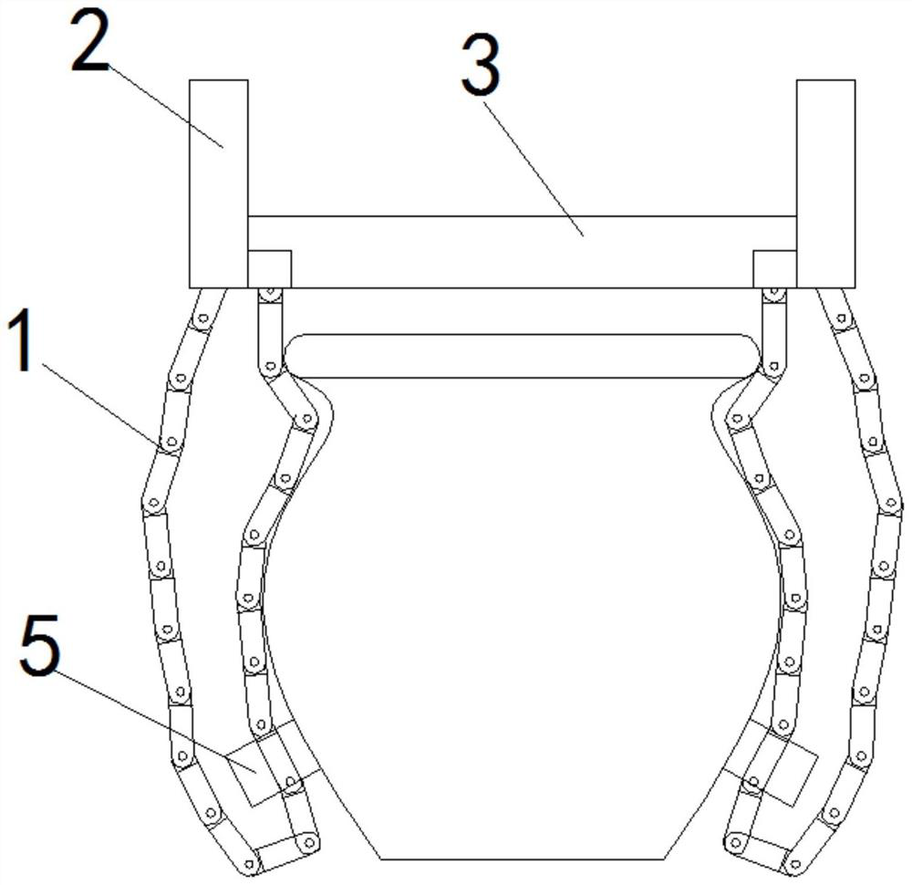
[0040] An adaptive intelligent grasping manipulator disclosed in this embodiment, combined with figure 1 As shown, specifically, it includes: a manipulator joint 1, a joint accommodation bin 2, a base 3 and a tracking vehicle 5, the base 3 is provided with several slideways, and several slideways are centered on the base 3 The center of the circle is arranged to divide the circle equally in the radial direction, and each slideway is provided with a joint accommodation bin 2, and a plurality of manipulator joints 1 are arranged in the joint accommodation bin 2, and several manipulator joints 1 are hingedly connected from head to tail to form a joint chain , one end of the joint chain is stored in the joint storage compartment 2, the other end of the joint chain is fixed at the opening of the joint storage compartment 2, and the joint chain is provided with a tracking vehicle 5; the base 3 is used as the overall support structure, and the base 3 Connect with the mobile structure...

specific Embodiment approach 2

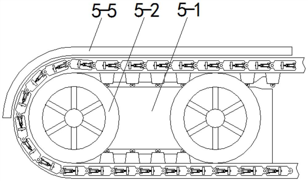
[0044] This embodiment is based on the specific implementation mode 1, specifically, in combination with Image 6 As shown, the outside of the articulated chain is covered with a rubber layer 6 .

specific Embodiment approach 3

[0045] This embodiment is based on the second specific implementation mode, specifically, in combination with Image 6 As shown, two groups of fixed block groups are arranged in parallel on one side of the rubber layer 6, and each group of fixed block groups includes several fixed blocks 6-1 arranged at intervals, and a fixed shaft body 6-2 is arranged on the upper end of the fixed block, The side of the car body 5-1 is provided with a shaft body chute 6-3, and the shaft body chute 6-3 goes around two wheels 5-2 shafts from the upper side of one end of the car body 5-1 and returns to The lower side of the starting end forms a U-shaped chute, the fixed shaft body 6-2 is embedded in the shaft body chute 6-3; the fixed shaft body 6-2 on the fixed block 6-1 is embedded in the shaft body chute 6-3 is used for the positioning of the articulated chain and the car body, while making the sliding of the tracking car 5 stable.


PUM


Abstract

The invention belongs to the technical field of manipulators, and in particular relates to a manipulator joint. A plurality of manipulator joints are hingedly connected to form a joint chain. A tracking vehicle is arranged on the joint chain. A locking shaft and a locking piece are arranged on the manipulator joint. There is a locking piece driving part, and the locking piece driving part is driven by the rotation of the magnetic wheel. There is a second magnetic wheel inside the tracking vehicle, and the second magnetic wheel is set correspondingly to the magnetic wheel. The fan; the tracking vehicle slides along the side wall of the pot from top to bottom, so that the joint chain forms a curve that fits the side wall of the pot, automatically adapts to the surface curve of the pot, and forms a grasping structure that converges at the lower end, avoiding The extra pressure generated by the clay pot locks the shape of the joint chain so that the clay pot can be grasped. At the same time, it has the adaptability of a flexible manipulator and the strength of a rigid manipulator to realize the grasping of the clay pot.

Description

technical field [0001] The invention belongs to the technical field of manipulators, in particular to a manipulator joint. Background technique [0002] Existing flexible manipulators usually use an air cavity inside the deformable material, and multiple drive chambers are set on one side of the air cavity. After the air source is introduced, the drive chamber expands to stretch the side wall of one side of the flexible manipulator. The manipulator bends to the other side. Because it uses flexible and bendable materials for grasping, it can grasp soft and fragile objects, but there are two problems with this type of manipulator: 1. The bending curve is fixed, for example, "a bow-shaped CN108381534 "flexible manipulator with continuous curved inner cavity. After the air source is introduced, the manipulator bends to achieve grasping, but the curved curve cannot adapt to the surface curve of the clay pot, and the point contact with the pottery pot makes the grasping unstable; ...

Claims


Application Information

Patent Timeline
Patent Type & Authority Patents(China)
IPC IPC(8): B25J15/00B25J17/02
CPCB25J15/0028B25J15/0033B25J17/0258
Inventor 赵静
Owner 常州今研精密机械有限公司
Why Eureka
Try Eureka