
A compliant manipulation device based on visual feedbacks and an automated detecting method for liquid bridge force

A visual feedback, operating device technology, applied in surface tension analysis, non-electric variable control, instruments, etc., can solve problems such as the inability to detect liquid bridge force in real time, and the inability to effectively guide operation tasks online.

Active Publication Date: 2018-12-21
SHANDONG UNIV OF TECH
View PDF7 Cites 0 Cited by
  • Summary
  • Abstract
  • Description
  • Claims
  • Application Information

AI Technical Summary

Problems solved by technology

[0004] The present invention aims to solve the problem that the traditional capillary force operation method cannot detect the liquid bridge force in real time, resulting in the inability to effectively guide the operation task online, and further provides a visual feedback-based compliant operation device and liquid bridge force automatic detection method

Method used


Image

  • A compliant manipulation device based on visual feedbacks and an automated detecting method for liquid bridge force
  • A compliant manipulation device based on visual feedbacks and an automated detecting method for liquid bridge force
  • A compliant manipulation device based on visual feedbacks and an automated detecting method for liquid bridge force

Examples


specific Embodiment approach 1

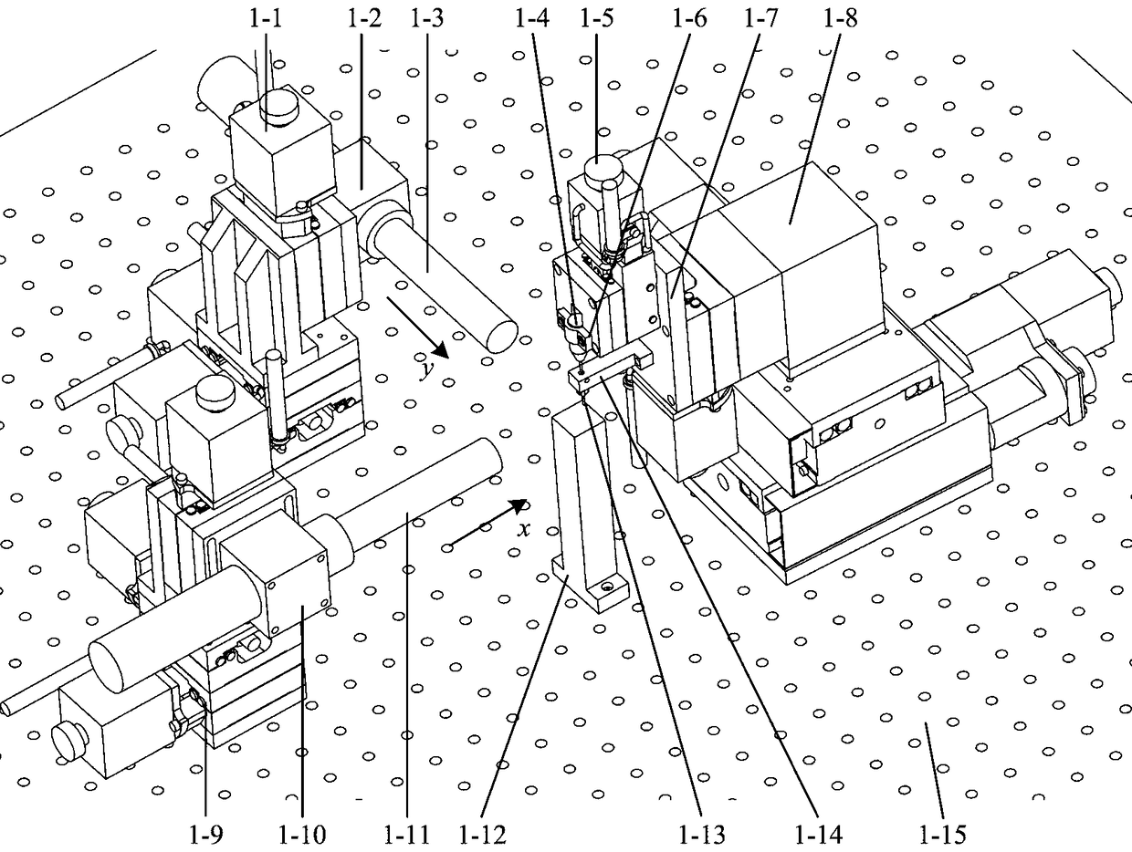
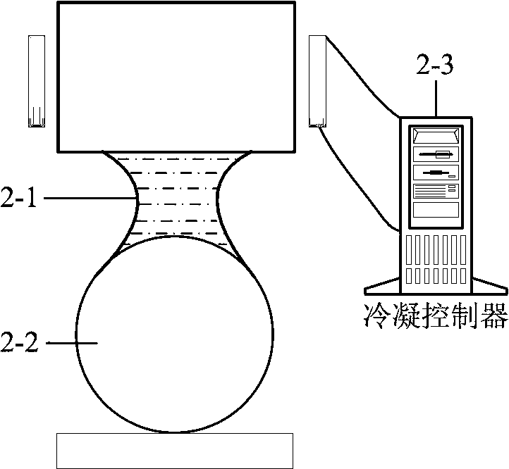
[0022] Specific implementation mode one: combine figure 1 and figure 2 Explain that a compliant operation device based on visual feedback in this embodiment includes a motion control module, a visual feedback module, an end effector module, a vibration isolation table 1-15, and an operation base (1-12). The motion control module includes an x-direction Three-axis precision electric platform 1-9, y-direction three-axis precision electric platform 1-1, operator three-axis precision electric platform 1-8, the visual feedback module includes x-direction microscope 1-11, x-direction microscope fixture 1-10, y direction microscope 1-3, y direction microscope fixture 1-2, the end effector module includes actuator adjustment motor 1-5, connecting plate 1-7, actuator chuck 1-4, chuck fixture 1-6, Condensation unit 1-14, condensation actuator 1-13, condensation controller 2-3; the x-direction three-axis precision electric platform 1-9, y-direction three-axis precision electric platfor...

specific Embodiment approach 2

[0023] Specific implementation mode two: combination figure 1 It is explained that the x-direction microscope 1-11 and the y-direction microscope fixture 1-2 of the compliant operation device based on visual feedback in this embodiment are arranged vertically in the same plane.

specific Embodiment approach 3

[0024] Specific implementation mode three: combination figure 1 and figure 2 It is explained that the temperature of the condensing unit 1-14 channels of a compliant operation device based on visual feedback in this embodiment is adjusted in real time by the condensing controller 2-3.


PUM


Abstract

Entitled by '' a compliant manipulation device based on visual feedbacks and an automated detecting method for liquid bridge force'', the invention relates to an automatic detection technique for compliant manipulation on objects in size of microns. The invention solves the conventional problem of passive reliance on droplet for next-step manipulation on capillary force without real-time detectionand feedback of liquid bridge force. The invention consists of a motion control module; a visual feedback module; an end actuator module; a vibration isolation table; manipulation block; a motion control module including x-direction triaxial precision electric platform, y-direction triaxial precision electric platform, and operator triaxial precision electric platform; a visual feedback module including x-dirction microscope, fixture for x-direction microscope, y-direction microscope, and fixture for y-direction microscope; and the end actuator module including actuator adjustment motor, connecting plate, actuator fixture, cartridge fixture, condensing unit, condensing actuator, and condensing controller. The invention can be used in automatic real-time detection of liquid bridge force for vision-based compliant manipulation of objects in size of microns.

Description

technical field [0001] The invention relates to an automatic detection technology for capillary force compliant operation, in particular to a visual feedback-based compliant operation device and a liquid bridge force automatic detection method. Background technique [0002] As a non-destructive micro-manipulation technology, the micro-object (0.1μm-1mm) manipulation method based on liquid bridge capillary force has operational flexibility and can effectively avoid local stress concentration caused by traditional mechanical clamping (clamps, vacuum adsorption, etc.) , to avoid damage to key features of micro-objects, and to be suitable for grasping micro-objects of different shapes. The existing capillary force manipulation methods are mainly divided into single-needle and capillary. The single-needle mainly uses the liquid medium obtained at the end of the operating probe to grasp the micro-objects; object. In order to evaluate the pick-up ability of micro-objects, it is n...

Claims


Application Information

Patent Timeline
IPC IPC(8): G01N13/02G05D23/24
CPCG01N13/02G05D23/24
Inventor 范增华田业冰李志永刘志强
Owner SHANDONG UNIV OF TECH
Learn More