
A water flow splitting device based on temperature control

A diversion device, temperature control technology, applied in the direction of valve operation/release device, valve device, valve details, etc., can solve the problems of water waste, instability, etc.

Active Publication Date: 2020-08-04
UNIV OF ELECTRONICS SCI & TECH OF CHINA
View PDF5 Cites 0 Cited by
  • Summary
  • Abstract
  • Description
  • Claims
  • Application Information

AI Technical Summary

Problems solved by technology

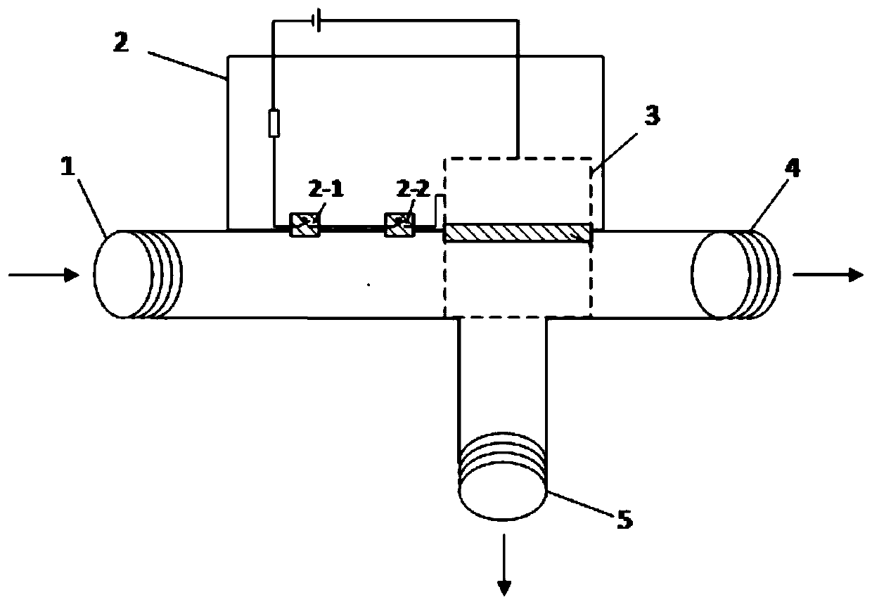
Because in many cases (such as barber shops), the control valve is far away from the actual water outlet such as showers, even if the control valve has adjusted the mixing ratio of cold and hot water to control the temperature, but in the case of intermittent water use, The actual water from the shower is hot and cold, and it is extremely unstable. It needs to let off a lot of water that is not suitable for the temperature. It is used after the water temperature is stable, so a lot of water is wasted.

Method used


Image

  • A water flow splitting device based on temperature control
  • A water flow splitting device based on temperature control

Examples


Embodiment Construction

[0019] In order to make the object, technical solution and advantages of the present invention clearer, the present invention will be further described in detail below in conjunction with the accompanying drawings and embodiments. It should be understood that the specific embodiments described here are only used to explain the present invention, not to limit the present invention.

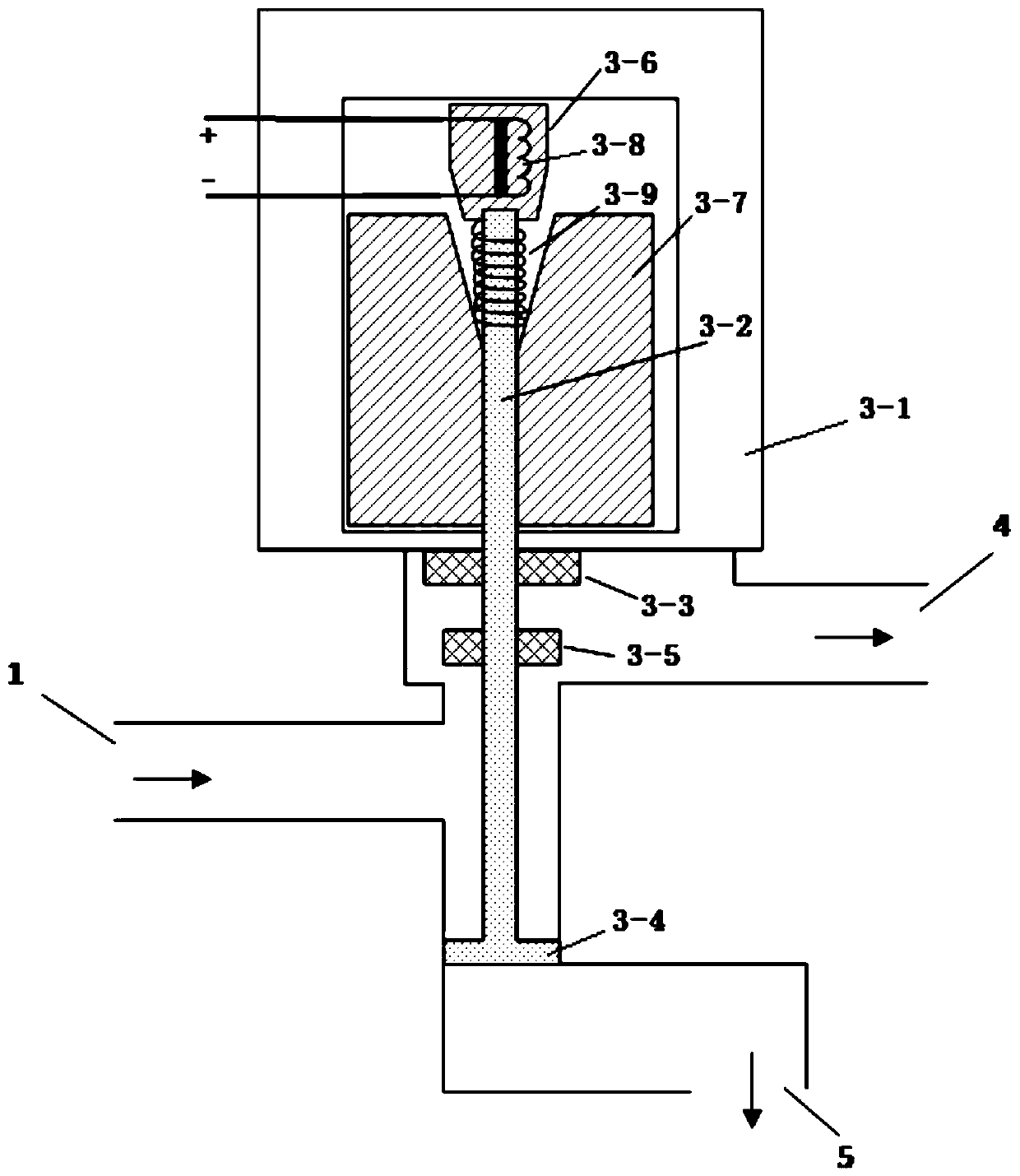
[0020] Such as figure 1 Shown is a schematic structural view of the water flow splitting device based on temperature control of the present invention. A water flow diversion device based on temperature control, comprising a water inlet pipe 1, a temperature sensing module 2, an electromagnetic control module 3, a first water outlet pipe 4 and a second water outlet pipe 5; The first water outlet pipe 4 communicates with the second water outlet pipe 5; the temperature sensing module 2 senses the temperature of the water body in the water inlet pipe 1, and generates a switch signal to control the ele...


PUM


Abstract

The invention discloses a water flow diversion device based on temperature control, which comprises a water inlet pipe, a temperature sensing module, an electromagnetic control module, a first water outlet pipe and a second water outlet pipe; The water pipe is connected to the second water outlet pipe; the temperature sensing module senses the temperature of the water body in the water inlet pipe, and generates a switch signal to control the electromagnetic control module to divert the water body. The invention automatically collects the water with unsuitable temperature through the first water outlet, and automatically flows out the water with suitable temperature from the second water outlet for use, so as to achieve the effect of intelligent water saving.

Description

technical field [0001] The invention belongs to the technical field of water flow diversion, and in particular relates to a water flow diversion device based on temperature control. Background technique [0002] In daily life, water heaters are generally installed far away from the faucet. For example, in a barber shop, when the service personnel turn on the faucet of the shampoo bed to serve customers, the water released from the nozzle may be too cold or too hot, and it takes a period of time to reach the desired temperature. Appropriate temperature, this will cause a lot of waste of water resources. [0003] The outlet of the water heater is connected to the water inlet of the faucet of the present invention through other control valves. Because in many cases (such as barber shops), the control valve is far away from the actual water outlet such as showers, even if the control valve has adjusted the mixing ratio of cold and hot water to control the temperature, but in th...

Claims


Application Information

Patent Timeline
Patent Type & Authority Patents(China)
IPC IPC(8): F16K31/06F16K31/66
CPCF16K31/002F16K31/0603
Inventor 蒋体钢张黎洁
Owner UNIV OF ELECTRONICS SCI & TECH OF CHINA
Learn More