Electrical connector

A technology for electrical connectors and contact sheets, which is applied to contact parts, bases/shells, etc., can solve the problems of shallow insertion depth and difficulty in ensuring insertion stability, so as to increase insertion depth and improve insertion stability. sexual effect

Pending Publication Date: 2019-01-04
ALLTOP ELECTRONICS SU ZHOU +1
View PDF0 Cites 1 Cited by
  • Summary
  • Abstract
  • Description
  • Claims
  • Application Information

AI Technical Summary

Problems solved by technology

[0002] In traditional power connectors, the contact part of the power terminal is set close to its socket, which leads to a sh

Method used


Image

  • Electrical connector
  • Electrical connector
  • Electrical connector

Examples


Embodiment Construction

[0027] The present invention will be described in detail below with reference to the embodiments shown in the accompanying drawings. However, this embodiment does not limit the present invention, and any structural, method, or functional changes made by those skilled in the art according to this embodiment are included in the protection scope of the present invention.

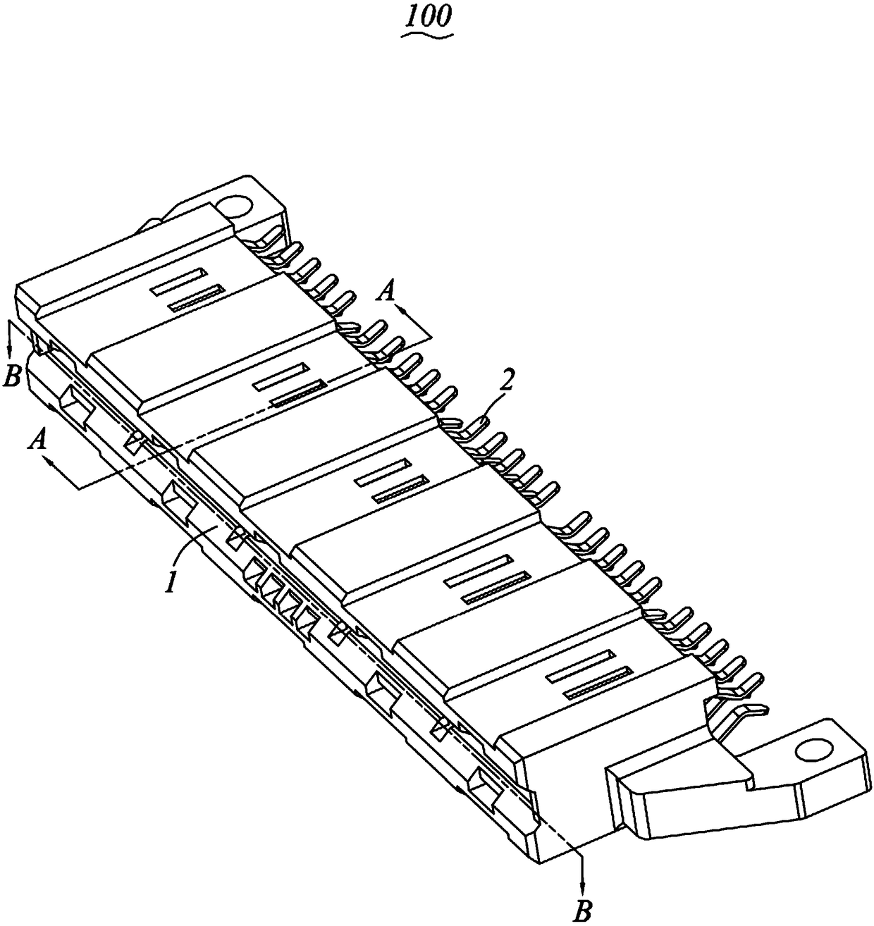
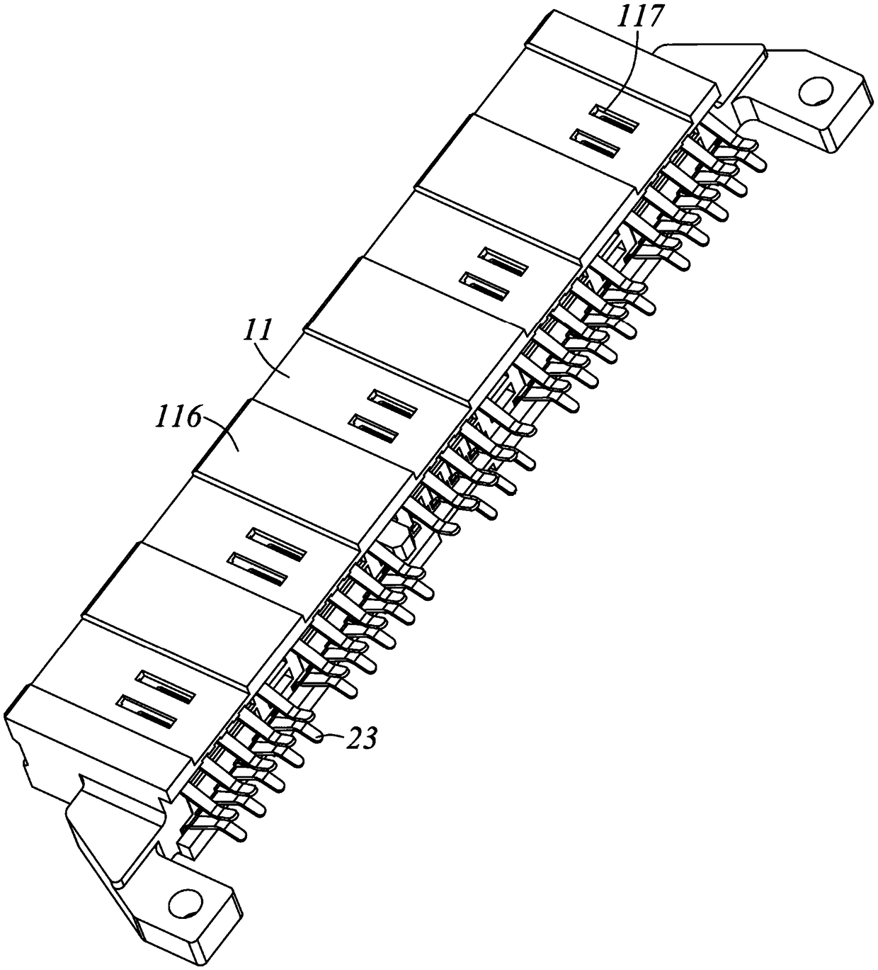
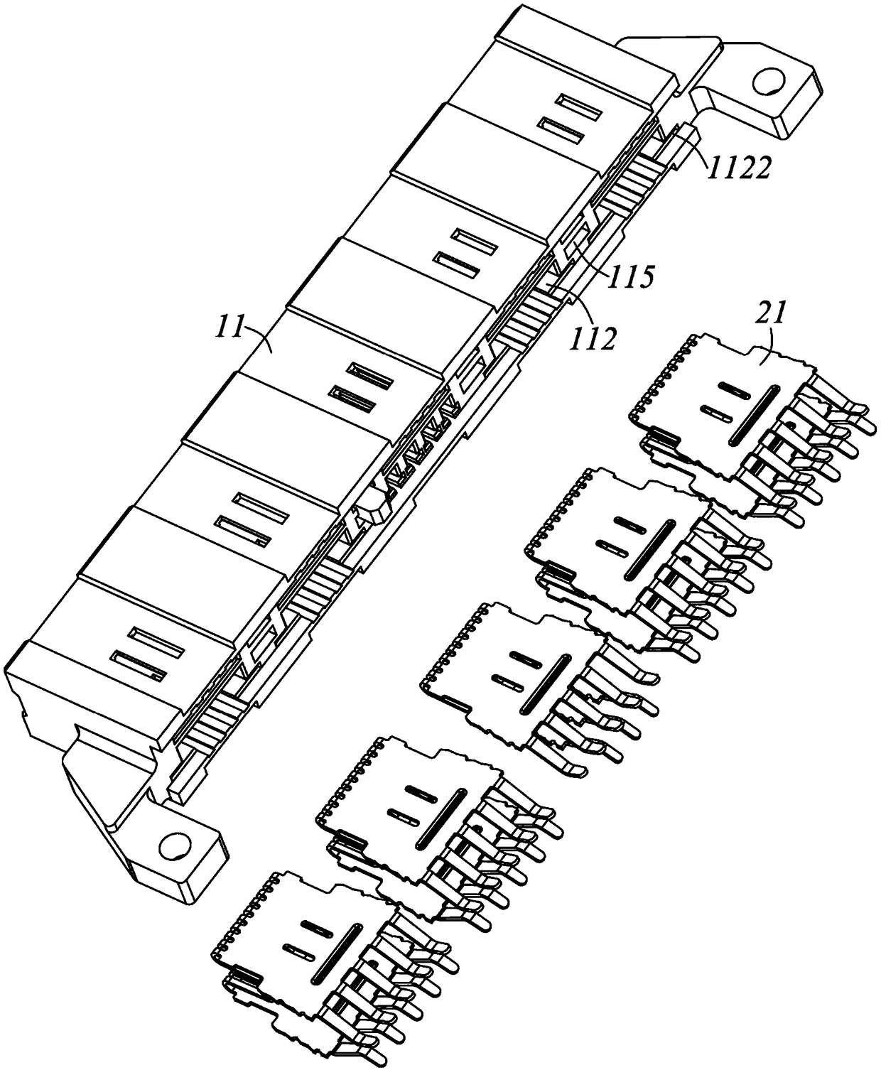
[0028] Please refer to Figure 1 to Figure 11 Shown is the electrical connector 100 of the present invention, which includes an insulating base body 1 and a plurality of power terminals 2 fixed on the insulating base body 1 . For ease of description, the following description will take the butt end of the electrical connector 100 as the front end, and the other end opposite to the butt end as the rear end for description, that is, the front and rear direction is the direction between the electrical connector 100 and the mating component (not shown). Inserting direction, at the same time, define a direction per...


PUM


Abstract

An electrical connector which has an insulating base body and a plurality of power supply terminals, the insulating base body has two oppositely disposed sidewalls, a docking cavity formed between thetwo sidewalls, the docking cavity is formed with an insertion interface into which a docking element is inserted, each of the power supply terminals is designed in a sheet shape, and has a fixing piece fixed to the side wall, A contact piece extending from one end of the fixing piece into the butt joint cavity and a welding pin extending from the other end of the fixing piece out of the insulating seat body, The contact pieces are formed by bending and extending from one end of an adjacent plug-in interface of the fixing piece toward a welding pin direction, and a plurality of contact portions arranged at lateral intervals are formed on each of the contact pieces, and the contact portions are arranged on the contact pieces away from the plug-in interface. The electrical connector of the invention can effectively improve the insertion stability.

Description

technical field [0001] The invention relates to an electrical connector. Background technique [0002] In traditional power connectors, the contact parts of the power terminals are located close to the plug interface, which leads to a shallow insertion depth when electrically connected to the mating component, and it is difficult to ensure the stability of the insertion. [0003] In view of this, it is necessary to improve the existing electrical connectors to solve the above problems. Contents of the invention [0004] The purpose of the present invention is to provide an electrical connector which can improve the insertion stability. [0005] In order to achieve the purpose of the above invention, the present invention provides an electrical connector, which includes an insulating base body and a plurality of power terminals, the insulating base body has two opposite side walls, and a pair of opposite sides formed between the two side walls. The docking cavity is forme...

Claims


Application Information

Patent Timeline
IPC IPC(8): H01R13/02H01R13/11H01R13/46
CPCH01R13/02H01R13/11H01R13/46
Inventor 郑义宏张志辉殷定彬游万益
Owner ALLTOP ELECTRONICS SU ZHOU
Why Eureka
Try Eureka