Roadbed reinforcing device for highway bridges

A technology for road bridges and reinforcement devices, which is applied to the cleaning method of tools, roads, roads, etc., can solve problems affecting the effect of reinforcement, affect the efficiency of construction, adjust the way of reinforcement, etc., to save production costs and materials, Improve adaptability and flexibility, improve the effect of reinforcement

Pending Publication Date: 2022-01-04
孙贝贝
View PDF1 Cites 0 Cited by
  • Summary
  • Abstract
  • Description
  • Claims
  • Application Information

AI Technical Summary

Problems solved by technology

[0003] Chinese invention patent CN202110820892.X discloses a soft soil subgrade reinforcement device, including: a first support plate, which is horizontally arranged on the surface of the soft soil subgrade, and a pair of vertical reinforcement piles are detachably arranged on the first support plate. The bottom of the reinforcement pile is inserted into the interior of the soft soil roadbed, and the top is detachably connected to the first support plate; the second support plate is arched and arranged on the first support plate and can be connected with the first support plate Disassembly and connection; reinforcement plates, which are a pair, a length-adjustable connecting rod is arranged between a pair of reinforcement plates, the bottom of a pair of reinforcement plates is detachably connected to the second support plate, and the top is inclined upward and parallel However, the structure of the subgrade reinforcement device used for the highway bridge is too traditional, and the reinforcement method cannot be quickly adjusted according to the road conditions and needs, which affects the effect of reinforcement, reduces the adaptability and flexibility of the reinforcement device, and affects the construction. Therefore, in view of the above status quo, there is an urgent need to develop a roadbed reinforcement device for highway bridges to overcome the shortcomings in current practical applications
[0004] Existing reinforcement devices for highway bridges cannot make adaptive changes according to the dynamic changes in road surface pressure during reinforcement and support, resulting in loosening of the reinforcement device and affecting the bearing effect of the road surface. At the same time, the existing reinforcement devices do not have weep holes , even if there is a drain hole, it does not have a dredging effect, which will cause water accumulation on the road and affect the drainage effect
[0005] And when the load force on the top of the support plate is different, the reinforcement device cannot adaptively adjust the support force of the support plate, so when the vehicle is constantly driving on the road surface and the load force on the top of the road surface is constantly changing, the reinforcement device itself will loosen, thereby affecting The safety performance of the entire reinforcement device

Method used


Image

  • Roadbed reinforcing device for highway bridges
  • Roadbed reinforcing device for highway bridges
  • Roadbed reinforcing device for highway bridges

Examples


no. 1 example

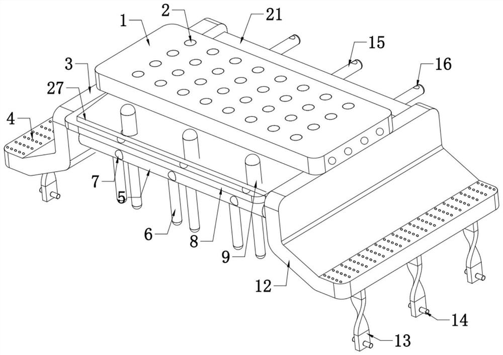
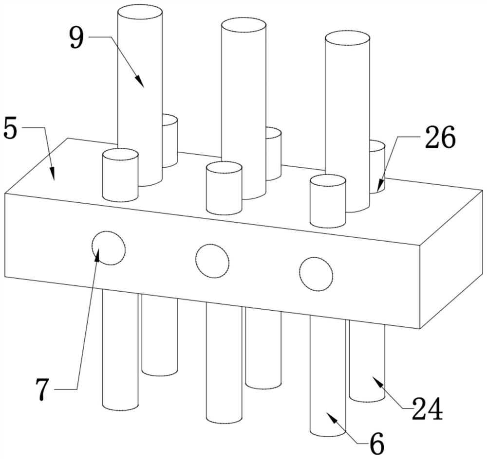
[0028] see Figure 1-5 , in an embodiment of the present invention, a roadbed reinforcement device for a highway bridge includes a support plate 1, a controller is provided on one side of the support plate 1, and the controller electrically controls each electrical component, and the two ends of the support plate 1 are provided with a second A reinforcing plate 3 and a second reinforcing plate 12, a fixing plate 5 is installed between the first reinforcing plate 3 and the second reinforcing plate 12, an insertion hole 7 is provided on one side of the fixing plate 5, and the fixing plate 5, the first reinforcing plate Between the plate 3 and the second reinforcing plate 12, a plug-in assembly for fixing the adjacent support plate 1 is also straddled. The first reinforcing plate 3 and the second reinforcing plate 12 are used to reinforce and fix the two ends of the roadbed. The top of the roadbed is The support plate 1 performs temporary support, thereby affecting the normal use...

no. 2 example

[0049] Based on the roadbed reinforcement device for road bridges provided in the first embodiment, in actual use, the discharge hole 2 will be blocked and the flow of water will not be smooth due to long-term use. The pressure exerted by the vehicle on the top of the support plate 1 will change dynamically, so that the steady state support of the bottom of the support plate 1 only by the support rod 9 obviously cannot meet the actual demand, and when the vehicle is running on the top of the support plate 1, the support plate 1 is paired with two The extrusion force of the first reinforcing plate 3 and the second reinforcing plate 12 on the side is also changing. In order to solve this problem, improve the dynamic stability of the roadbed and the smoothness of the discharge hole 2 in actual use, the road bridge The roadbed reinforcement device used also includes: the top of the support plate 1 is evenly arrayed with multiple groups of pressure sensors to detect the pressure val...


PUM


Abstract

The invention relates to the technical field of roadbed reinforcing devices, in particular to a roadbed reinforcing device for highway bridges. Theroadbed reinforcing device comprises a support plate, a plurality of groups of pressure sensors are uniformly arrayed at the top of the support plate, a controller is arranged on one side of the support plate, and a first reinforcing plate and a second reinforcing plate are arranged at two ends of the support plate. A fixing plate is arranged between the first reinforcing plate and the second reinforcing plate, an inserting hole is formed in one side of the fixing plate, a supporting rod is arranged at the top of the fixing plate, multiple sets of through holes are formed in the top of the fixing plate, a first sliding rod and a second sliding rod are slidably connected into the through holes respectively, a first wedge-shaped groove is formed in the first sliding rod, and a second wedge-shaped groove is formed in the second sliding rod. According to the device, the top of the support plate can be temporarily and stably supported, the dynamic load of the top of the supporting plate can be adaptively adjusted, the supporting and reinforcing effect is improved, blockage clearing is conducted on the discharge hole, the cleanliness of the device is improved, and the drainage smoothness of the device is guaranteed.

Description

technical field [0001] The invention relates to the technical field of roadbed reinforcement devices, in particular to a roadbed reinforcement device for highway bridges. Background technique [0002] The subgrade is the load-bearing body of the road. The roadbed is composed of width, height and slope. Whether the roadbed is solid or not directly affects the service life of the road, so the roadbed needs to be reinforced after the completion of the road construction, so that the service life of the road is longer. [0003] Chinese invention patent CN202110820892.X discloses a soft soil subgrade reinforcement device, including: a first support plate, which is horizontally arranged on the surface of the soft soil subgrade, and a pair of vertical reinforcement piles are detachably arranged on the first support plate. The bottom of the reinforcement pile is inserted into the interior of the soft soil roadbed, and the top is detachably connected to the first support plate; the ...

Claims


Application Information

Patent Timeline
Patent Type & Authority Applications(China)
IPC IPC(8): E01C3/00E01C3/04E01C3/06B08B1/00
CPCE01C3/00E01C3/04E01C3/06B08B1/001
Inventor 孙贝贝杨浩杨心平周伍莹谭涛王晓鸽曹雪芹蒋悦然魏志福王博
Owner 孙贝贝
Why Eureka
Try Eureka