Orthopedic automatic retractor

A retractor, automatic technology, applied in medical science, surgery, etc., can solve problems such as inconvenience in use

Inactive Publication Date: 2019-01-11
王仁浒
View PDF5 Cites 0 Cited by
  • Summary
  • Abstract
  • Description
  • Claims
  • Application Information

AI Technical Summary

Problems solved by technology

The retractor is used to retract the tissue and reveal the surgical field of view. However, the general retractor can only achieve retraction in one direction, which is not very convenient to use

Method used


Image

  • Orthopedic automatic retractor
  • Orthopedic automatic retractor

Examples


Embodiment Construction

[0017] In order to make the above objects, features and advantages of the present invention more clearly understood, the specific embodiments of the present invention will be described in detail below with reference to the accompanying drawings. In the following description, numerous specific details are set forth in order to provide a thorough understanding of the present invention.

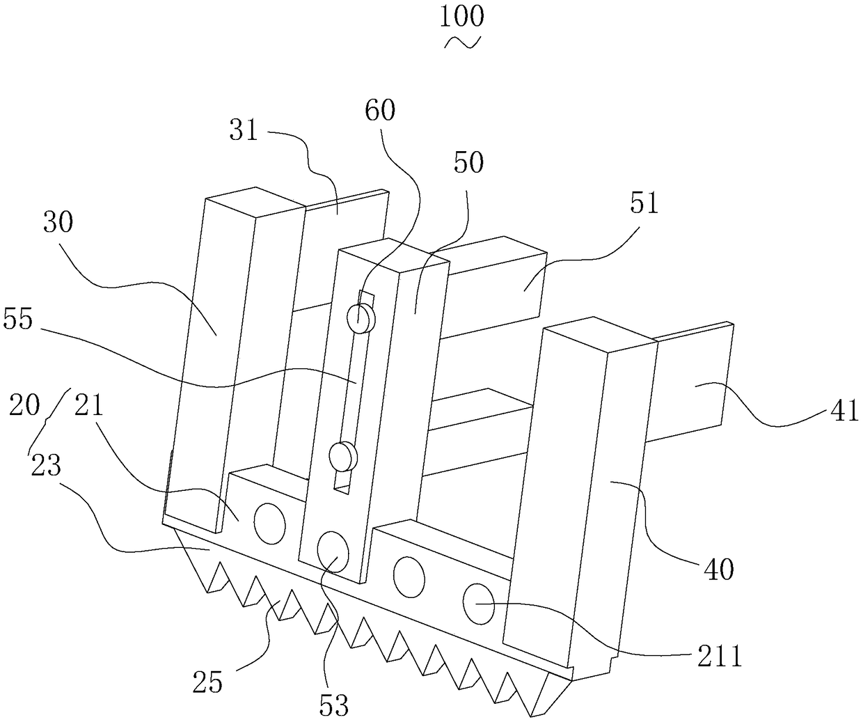
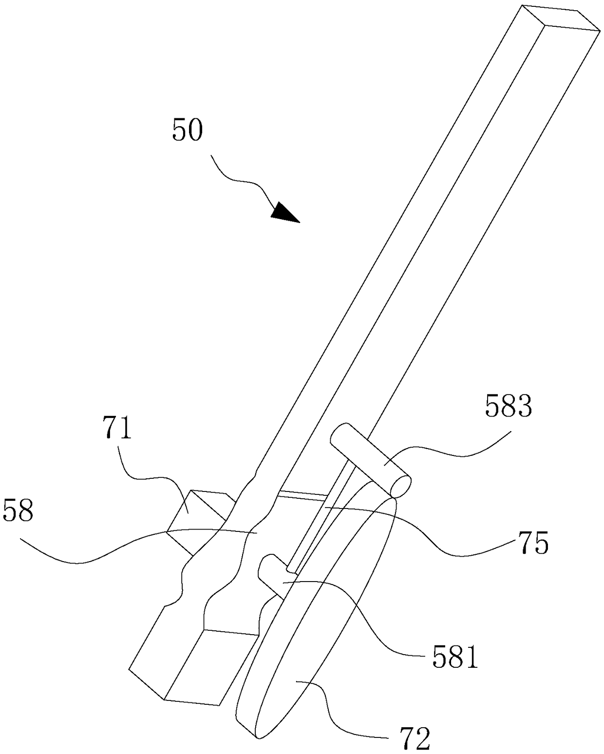
[0018] The invention relates to an orthopedic automatic retractor. For example, the orthopaedic automatic retractor includes a rack, a fixed bar, a moving bar and an auxiliary bar. For example, a plurality of meshing teeth are formed on the rack, the fixing bar is vertically fixed to one end of the rack, an end of the fixing bar is provided with a first retracting claw, and the moving bar slides arranged on the rack. For example, the end of the moving bar is provided with a second retracting claw, the moving bar is arranged in parallel with the fixing bar, and the auxiliary bar is slidably arr...


PUM


Abstract

The invention relates to an orthopedic automatic retractor. The orthopaedic automatic retractor includes a rack, a fixing bar, a mobile bar and an auxiliary bar, wherein a plurality of engaging teethare formed on the rack; the fixing bar is vertically fixed to one end of the rack; the end of the fixing bar is provided with a first retracting jaw; the moving bar is slidably arranged on the rack; the end of the moving bar is provided with a second retracting jaw, and the moving bar is arranged in parallel with the fixing bar; and the auxiliary bar is slidably arranged on the rack and between the fixing bar and the moving bar. The orthopedic automatic retractor is convenient to use.

Description

technical field [0001] The invention relates to an orthopedic automatic retractor. Background technique [0002] Surgical retractors are common in orthopaedic surgery. For example, in thoracic surgery, it is often necessary to open between the ribs and use a retractor to spread the ribs. The retractor is used to retract the tissue and reveal the surgical field. However, the general retractor can only achieve retraction in one direction, which is inconvenient to use. SUMMARY OF THE INVENTION [0003] Based on this, it is necessary to provide a more convenient orthopaedic automatic retractor. [0004] An orthopaedic automatic retractor includes a rack, a fixed rack, a moving rack and an auxiliary rack, wherein a plurality of meshing teeth are formed on the rack, the stationary rack is vertically fixed to one end of the rack, and the fixed rack is The end of the bar is provided with a first retracting claw, the moving bar is slidably arranged on the rack, the end of the mov...

Claims


Application Information

Patent Timeline
Patent Type & Authority Applications(China)
IPC IPC(8): A61B17/02
CPCA61B17/025
Inventor 瓮秀山
Owner 王仁浒
Why Eureka
Try Eureka