Fixing frame for illuminating lamp in construction site

A technology for lighting lamps and construction sites, which is applied in the parts of lighting devices, lighting applications, lighting devices, etc., can solve the problems of lighting blockage, lights shaking, construction workers, and lack of light, and achieves the ability to prevent left and right shaking. Effect

Active Publication Date: 2019-01-11
五河县智凯环保科技有限公司
View PDF7 Cites 6 Cited by
  • Summary
  • Abstract
  • Description
  • Claims
  • Application Information

AI Technical Summary

Problems solved by technology

[0003] In order to overcome the shortcoming that the lighting lamp is easily affected by external factors and shakes from side to side, which will cause the light to dazzle the eyes of construction workers, part of the light of the lighting lamp is blocked, and some construction points may not be illuminated. The technical problem to be solved is: to provide a A fixing frame for construction site lighting fixtures that can prevent the lighting lamp from shaking from side to side and can focus the lighting lamp

Method used


Image

  • Fixing frame for illuminating lamp in construction site
  • Fixing frame for illuminating lamp in construction site
  • Fixing frame for illuminating lamp in construction site

Examples


Embodiment 1

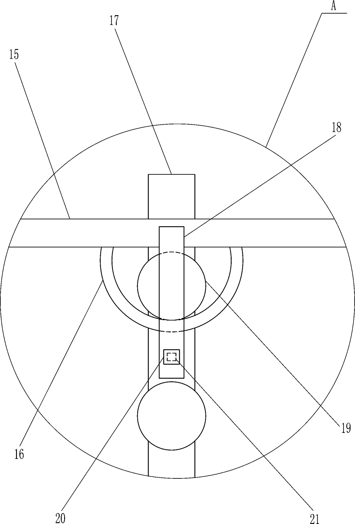
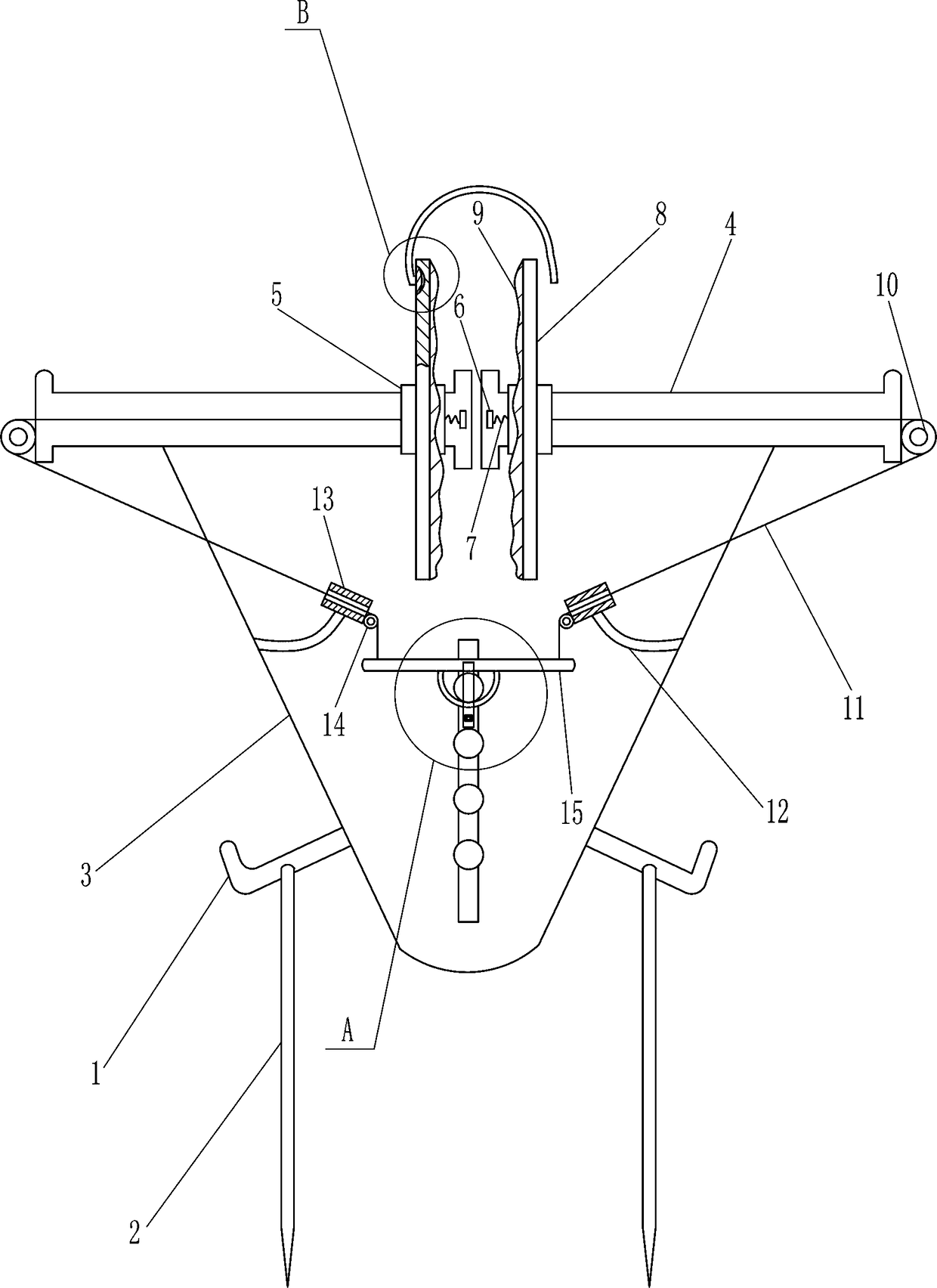
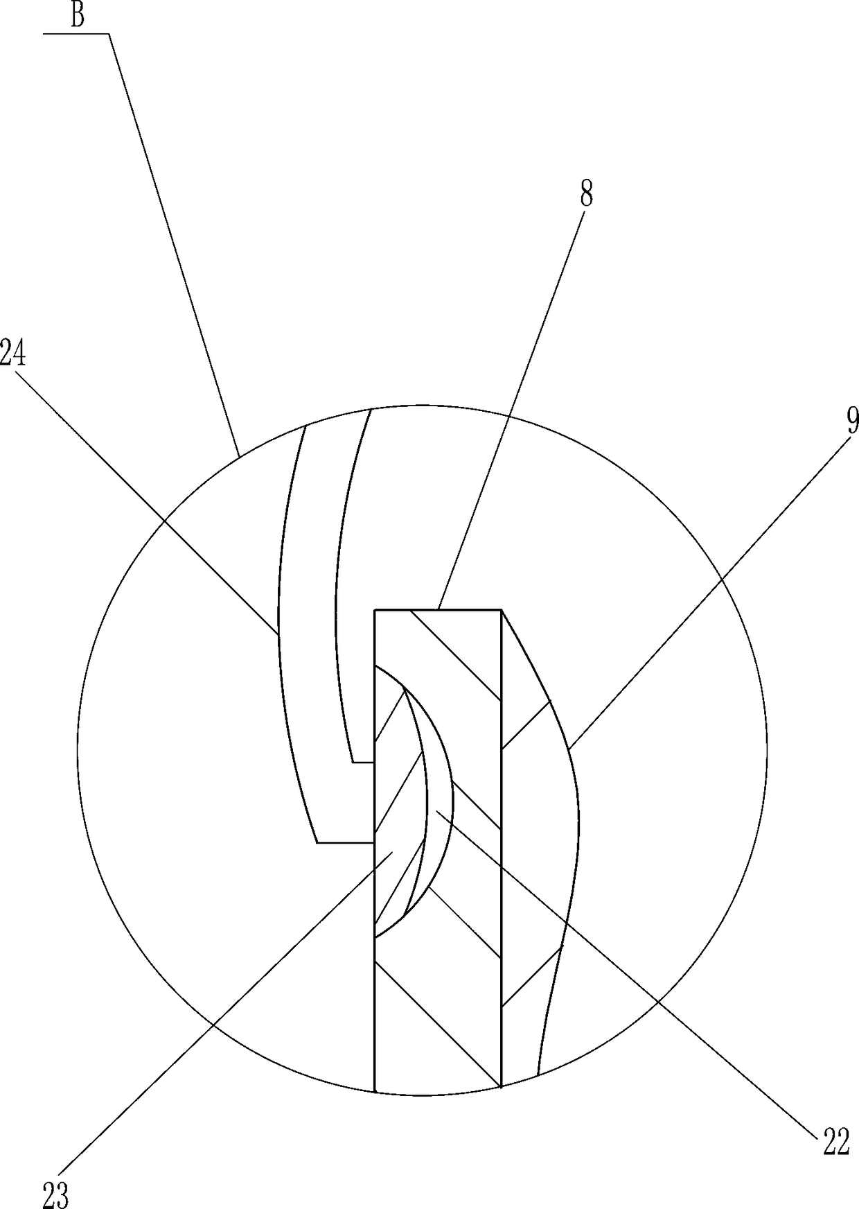
[0017] A fixing frame for construction site lighting fixtures, such as Figure 1-3 As shown, it includes a fixed rod 1, an insert rod 2, a mounting column 3, a slide rail 4, a slider 5, a bump 6, a spring 7, a splint 8, a cushion 9, a guide wheel 10, a pull cord 11, and a support rod 12 , guide sleeve 13, fixed pulley 14 and pull rod 15, the left and right sides bottoms of mounting column 3 are all connected with fixed rod 1, the front and rear sides of fixed rod 1 are all connected with insertion rod 2, the top left and right sides of mounting column 3 are all connected A slide rail 4 is connected, and a slide block 5 is slidably connected to the slide rail 4. The right part of the left slide rail 4 and the left part of the right slide rail 4 are connected with a bump 6, and the bump 6 and the slide block 5 A spring 7 is connected between them, a splint 8 is connected to the front side of the slider 5, a cushion 9 is connected to the right side of the left splint 8 and the le...

Embodiment 2

[0019] A fixing frame for construction site lighting fixtures, such as Figure 1-3 As shown, it includes a fixed rod 1, an insert rod 2, a mounting column 3, a slide rail 4, a slider 5, a bump 6, a spring 7, a splint 8, a cushion 9, a guide wheel 10, a pull cord 11, and a support rod 12 , guide sleeve 13, fixed pulley 14 and pull rod 15, the left and right sides bottoms of mounting column 3 are all connected with fixed rod 1, the front and rear sides of fixed rod 1 are all connected with insertion rod 2, the top left and right sides of mounting column 3 are all connected A slide rail 4 is connected, and a slide block 5 is slidably connected to the slide rail 4. The right part of the left slide rail 4 and the left part of the right slide rail 4 are connected with a bump 6, and the bump 6 and the slide block 5 A spring 7 is connected between them, a splint 8 is connected to the front side of the slider 5, a cushion 9 is connected to the right side of the left splint 8 and the le...

Embodiment 3

[0022] A fixing frame for construction site lighting fixtures, such as Figure 1-3 As shown, it includes a fixed rod 1, an insert rod 2, a mounting column 3, a slide rail 4, a slider 5, a bump 6, a spring 7, a splint 8, a cushion 9, a guide wheel 10, a pull cord 11, and a support rod 12 , guide sleeve 13, fixed pulley 14 and pull rod 15, the left and right sides bottoms of mounting column 3 are all connected with fixed rod 1, the front and rear sides of fixed rod 1 are all connected with insertion rod 2, the top left and right sides of mounting column 3 are all connected A slide rail 4 is connected, and a slide block 5 is slidably connected to the slide rail 4. The right part of the left slide rail 4 and the left part of the right slide rail 4 are connected with a bump 6, and the bump 6 and the slide block 5 A spring 7 is connected between them, a splint 8 is connected to the front side of the slider 5, a cushion 9 is connected to the right side of the left splint 8 and the le...


PUM


Abstract

The invention relates to a fixing frame for an illuminating lamp, in particular to a fixing frame for an illuminating lamp in a construction site. According to the fixing frame for the illuminating lamp in the construction site, the illuminating lamp can be prevented from shaking leftwards and rightwards, and light of the illuminating lamp can be gathered. According to the technical scheme, the fixing frame for the illuminating lamp in the construction site comprises fixing rods, inserting rods, a mounting column, sliding rails, sliding blocks, protruding blocks, springs, clamping plates and the like. The lower portions of the left side and the right side of the mounting column are connected with the fixing rods correspondingly, the front sides and the rear sides of the fixing rods are connected with the inserting rods correspondingly, the left side and the right side of the top of the mounting column are connected with the sliding rails correspondingly, and the sliding blocks are slidably connected to the sliding rails. According to the fixing frame for the illuminating lamp in the construction site, by pulling a pull rod downwards, pull ropes drive the sliding blocks on the leftside and the right side and parts on the sliding blocks to move away from one another, then a user places the illuminating lamp between the clamping plates on the left side and the right side, the clamping plates on the left side and the right side are reset under the effect of the springs to fix illuminating lamp, and in this way, the illuminating lamp can be prevented from shaking leftwards andrightwards.

Description

technical field [0001] The invention relates to a fixing frame for lighting lamps, in particular to a fixing frame for lighting lamps on construction sites. Background technique [0002] When construction workers are working on a construction site at night, they generally need lighting to prevent mistakes during construction. At present, the lighting on a construction site is generally hung on a pole, so that the lighting is easily affected by external factors and shakes left and right, thus It causes the light to dazzle the eyes of construction workers. At present, construction workers usually use two support plates to clamp and fix the lighting lamp, but this will block part of the light of the lighting lamp and cannot concentrate the light. Some construction points may illuminate Less than that, it is easy to cause construction workers to make construction mistakes and may also cause safety accidents. Contents of the invention [0003] In order to overcome the disadvan...

Claims


Application Information

Patent Timeline
Patent Type & Authority Applications(China)
IPC IPC(8): F21S8/00F21V14/02F21V21/14F21V21/36F21W131/402
CPCF21S8/00F21V14/02F21V21/14F21V21/36F21W2131/402
Inventor 詹凤程
Owner 五河县智凯环保科技有限公司
Why Eureka
Try Eureka