A pixel charging method and an electronic device

A technology for charging electronic devices and pixels, which is applied in the field of communication and can solve problems such as insufficient charging time for sub-pixels.

Active Publication Date: 2019-01-11
VIVO MOBILE COMM CO LTD
View PDF12 Cites 22 Cited by
  • Summary
  • Abstract
  • Description
  • Claims
  • Application Information

AI Technical Summary

Problems solved by technology

[0004] Embodiments of the present invention provide a pixel charging method and

Method used


Image

  • A pixel charging method and an electronic device
  • A pixel charging method and an electronic device
  • A pixel charging method and an electronic device

Examples


Embodiment approach 1

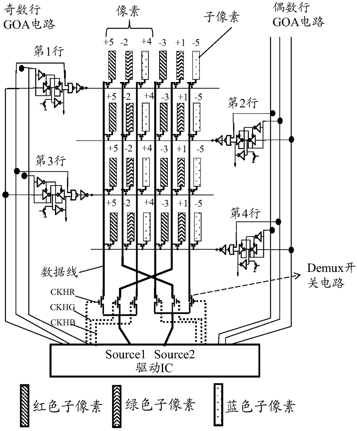
[0125] Embodiment 1: The electronic device controls the display of the i-th picture frame by means of column inversion driving. That is, the potential polarities of adjacent columns are opposite.

[0126] In this embodiment, optionally, the method further includes:

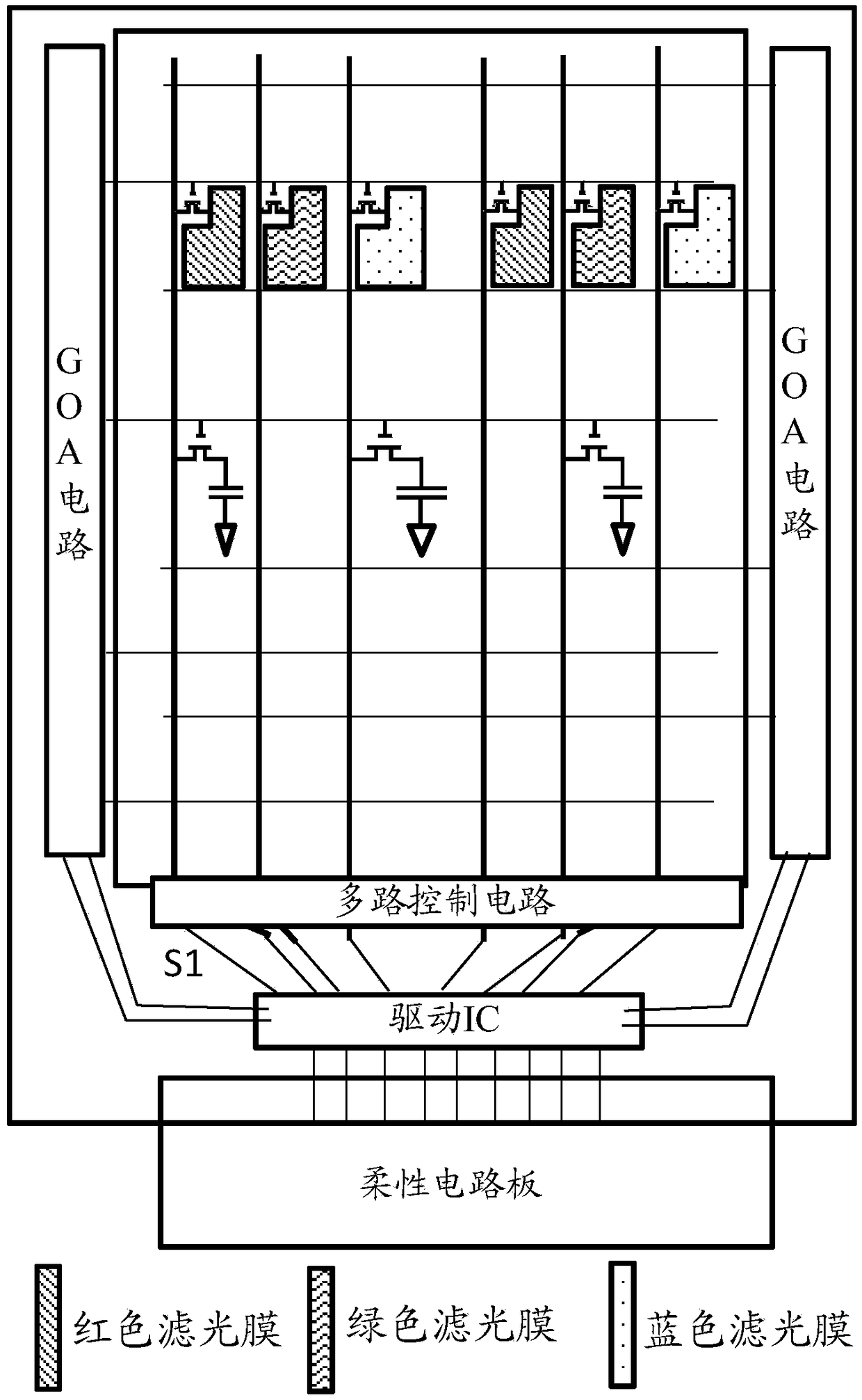
[0127] When the gates included in the display module are turned on, the multi-channel control circuit sequentially provides voltage signals of the first preset polarity to the odd-numbered column data lines in the M data lines, and the multi-channel control circuit The circuit sequentially provides the voltage signals of the second preset polarity to the data lines of the even columns in the M data lines;

[0128] Wherein, the first preset polarity is opposite to the second preset polarity. The first preset polarity and the second preset polarity may be predetermined by the electronic device. If the first preset polarity is positive, the second preset polarity is negative; if the first preset polarity is Negati...

Embodiment approach 2

[0145] Embodiment 2: The electronic device controls the display of the i-th picture frame by means of line inversion driving. That is, the potential polarities of adjacent rows are opposite.

[0146] In this embodiment, optionally, the method further includes:

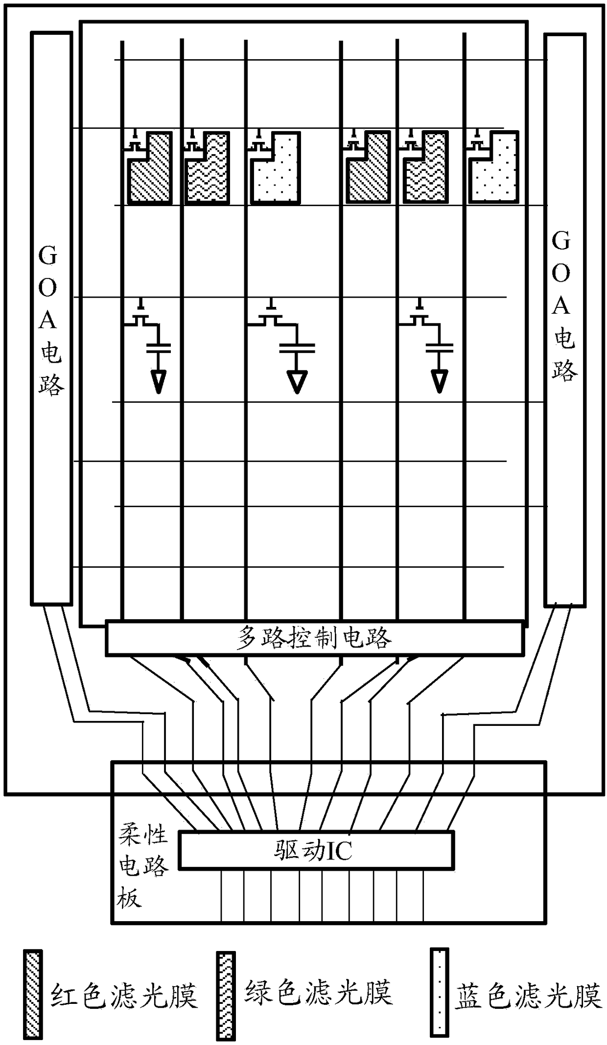
[0147]During the display process of the i-th picture frame, when the gates of the odd-numbered rows included in the display module are turned on, the multi-channel control circuit sequentially provides voltage signals of the first preset polarity to the M data lines ; Under the condition that the gates of the even-numbered rows included in the display module are turned on, the multi-channel control circuit sequentially provides the voltage signals of the second preset polarity to the M data lines;

[0148] Wherein, the first preset polarity is opposite to the second preset polarity, and i is a positive integer. For details, refer to the description in Embodiment 1, which will not be repeated here.

[0149] In this e...

Embodiment approach 3

[0160] Embodiment 3: The electronic device controls the display of the i-th picture frame and the i+1-th picture frame by means of frame inversion driving. That is, the potential polarities of adjacent picture frames are opposite.

[0161] In this embodiment, optionally, the method further includes:

[0162] During the display process of the i-th frame, when the gates included in the display module are turned on, the multiplex control circuit sequentially provides voltage signals of the first preset polarity to the M data lines;

[0163] During the display process of the i+1th frame, when the gates included in the display module are turned on, the multi-channel control circuit sequentially provides the M data lines with voltage signals of the second preset polarity ;

[0164] Wherein, the first preset polarity is opposite to the second preset polarity, and i is a positive integer. That is, when the first preset polarity is positive, the second preset polarity is negative; w...


PUM


Abstract

The invention provides a pixel charging method and an electronic device. The method comprises the following steps: determining the polarity of a voltage signal supplied by a multiplexing control circuit to a target data line among M data lines; if the polarity is the first polarity, controlling the duration of the voltage signal supplied to the target data line to be equal to the first charging duration; If the polarity is the second polarity, controlling the duration of the voltage signal supplied to the target data line to be equal to the second charging duration; the first charge duration is longer than the first minimum charge duration required when the sub-pixel is charged by the voltage signal of the first polarity; the second charge duration is longer than that of the sub-pixel whenthe sub-pixel is charged by the voltage signal of the second polarity, and the second minimum charge duration is smaller than that of the predetermined charge duration. The predetermined charge duration is longer than the second minimum charge duration and smaller than the first minimum charge duration. The invention can ensure that the sub-pixel charging time is sufficient.

Description

technical field [0001] Embodiments of the present invention relate to the field of communication technologies, and in particular, to a pixel charging method and an electronic device. Background technique [0002] When the display module is displaying, a driver IC (Integrated Circuit, integrated circuit) in the display module writes a voltage signal to each sub-pixel, charges the sub-pixel, and then controls the sub-pixel to display. [0003] However, in the prior art, there is a problem that the charging time of the sub-pixels is insufficient. SUMMARY OF THE INVENTION [0004] Embodiments of the present invention provide a pixel charging method and an electronic device to solve the problem of insufficient sub-pixel charging time. [0005] In order to solve the above-mentioned problems, the present invention is realized as follows: [0006] In a first aspect, an embodiment of the present invention provides a pixel charging method, which is applied to an electronic device....

Claims


Application Information

Patent Timeline
IPC IPC(8): G09G3/36G09G3/3208
CPCG09G3/3208G09G3/3648G09G3/3696
Inventor 文亮李冠恒
Owner VIVO MOBILE COMM CO LTD
Why Eureka
Try Eureka