
Multifunctional cutting machine

A cutting machine, multi-functional technology, applied in the direction of metal sawing equipment, sawing machine, metal processing equipment, etc., can solve the problems of increased distance, reduced cutting efficiency, simple structure and insufficient functions

Pending Publication Date: 2019-01-18
翟秋朗
View PDF0 Cites 0 Cited by
  • Summary
  • Abstract
  • Description
  • Claims
  • Application Information

AI Technical Summary

Problems solved by technology

[0002] In the production of aluminum alloy doors and windows, furniture and the cutting of aluminum alloy profiles, it is often necessary to achieve 90-degree angle cutting, 45-degree angle cutting, and cutting at any angle. The existing cutting equipment usually uses saw blades from the back to the front The feeding method of translation or swing operation, or translation or swing operation from front to back, or lift or swing operation from bottom to top, although there are also devices that lift vertically from top to bottom, its structural feature is that the two saw blades only Fixed 90-degree angle and staggered up and down for a certain distance, the two saw blades cannot change the angle, so the disadvantages brought by the above structure and feeding method are: (1) The increased cutting distance of the saw blade reduces the cutting efficiency, (2) No change in angle cannot meet the requirements Use needs, (3) the structure is simple and the function is not perfect enough, so it is extremely necessary to add a cutting machine that can solve the above shortcomings

Method used


Image

  • Multifunctional cutting machine
  • Multifunctional cutting machine
  • Multifunctional cutting machine

Examples


Embodiment Construction

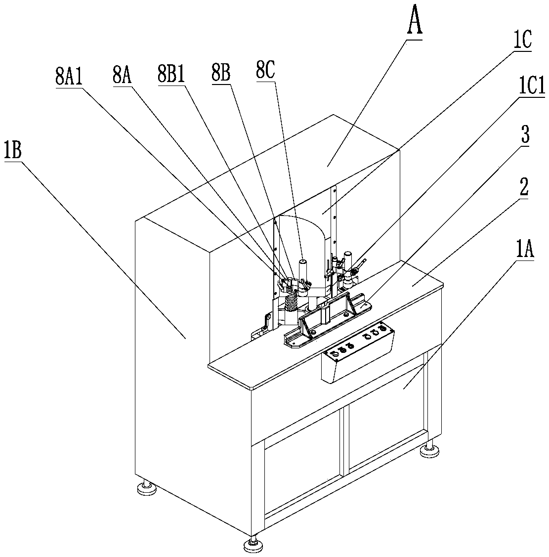
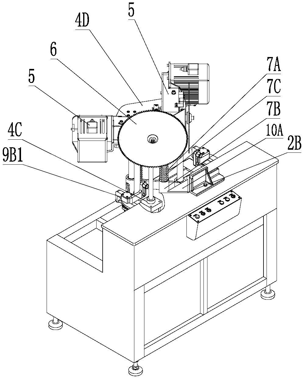
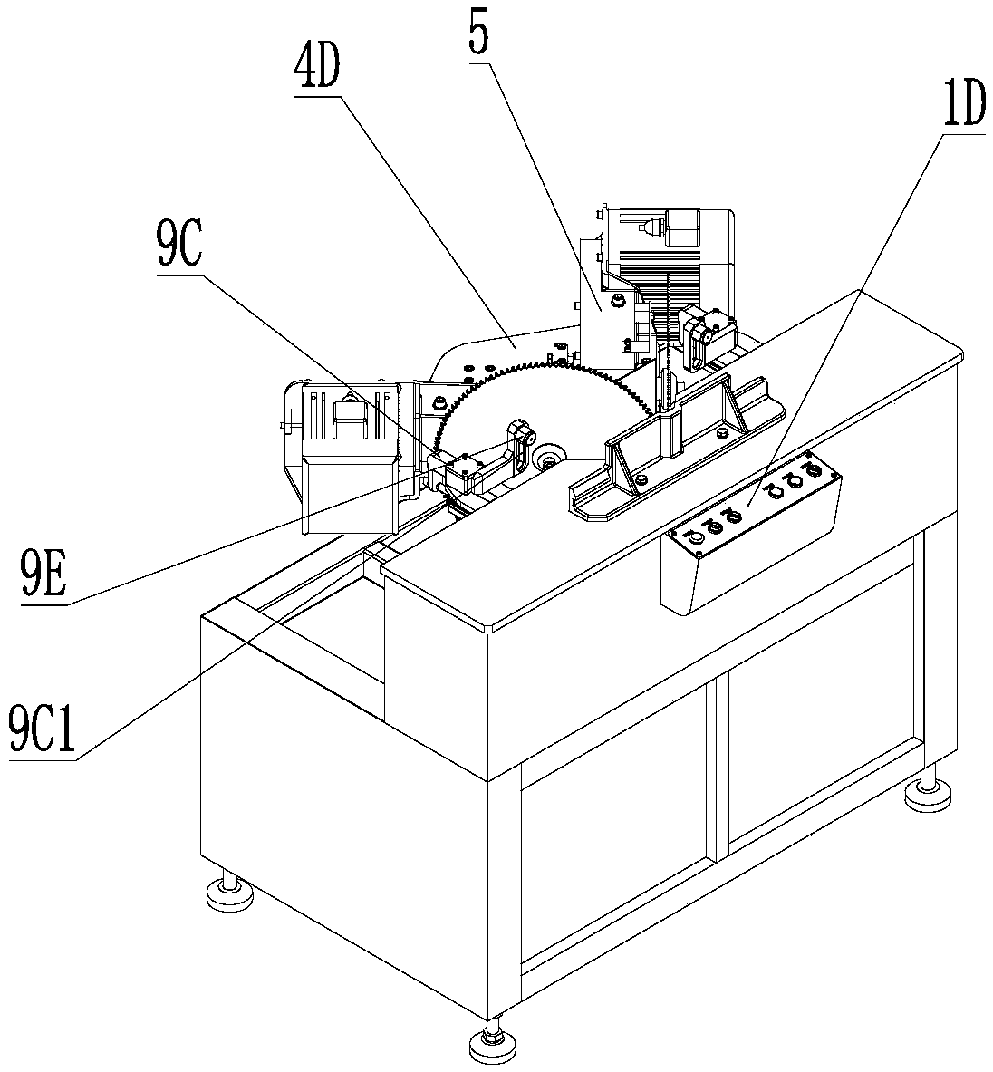
[0051] see figure 1 , figure 2 , image 3 , Figure 4 , Embodiment 1 is a cutting machine A with two power assemblies and two saw blades placed on a lifting mechanism, and simultaneously displays the shape of the whole machine, lifting mechanism, elastic device, swing vertical pressing device, horizontal pressing device, The remaining material falling delay device, the vertical section of the remaining material falling guide trough, the small lifting shield, etc. are placed on the front of the frame 1A. The front part of the cutting machine is removed from the coaming plate 1B, the shield 1C, and the small lifting shield 1C1 to show that the lifting guide seat 4A is vertically placed in the rear portion 1A1 of the workbench 2 frame with its guide post hole 4A1, and the lifting guide The column 4B is placed in the guide column hole 4A1 of the lifting guide seat, and the lifting plate 4D is connected to the upper part of the lifting guide column 4B. The cylinder 4C1 in the l...


PUM


Abstract

The invention discloses a multifunctional cutting machine comprising a frame, a worktable, a seat, a lifting mechanism, a power assembly, and a saw blade, wherein the worktable is arranged on the front portion of the frame; the seat is arranged on the worktable; the saw blade is disposed on the power assembly; the lifting mechanism includes a lifting guide seat, a lifting guide pillar, and a lifting power device, and is characterized in that a vertical guide pillar hole is disposed in the lifting guide seat, the lifting guide seat is disposed on the frame, the lifting guide pillar is disposedin the guide pillar hole, and the power assembly is disposed on the upper portion of the lifting guide pillar, the lifting power device is disposed between the lifting guide seat and the power assembly, the lifting guide pillar and the power assembly are vertically lifted and lowered by the lifting power device, and the saw blade disposed on the power assembly moves from top to bottom so as to cuta material on the surface of the worktable. The multifunctional cutting machine has various forms, and is versatile and powerful in functions.

Description

technical field [0001] The invention relates to mechanical processing equipment, in particular to aluminum alloy profile cutting equipment, in particular to a multifunctional cutting machine. Background technique [0002] In the production of aluminum alloy doors and windows, furniture and the cutting of aluminum alloy profiles, it is often necessary to achieve 90-degree angle cutting, 45-degree angle cutting, and cutting at any angle. The existing cutting equipment usually uses saw blades from the back to the front The feeding method of translation or swing operation, or translation or swing operation from front to back, or lift or swing operation from bottom to top, although there are also devices that lift vertically from top to bottom, its structural feature is that the two saw blades only Fixed 90-degree angle and staggered up and down for a certain distance, the two saw blades cannot change the angle, so the disadvantages brought by the above structure and feeding meth...

Claims


Application Information

Patent Timeline
IPC IPC(8): B23D45/14
CPCB23D45/143B23D45/022
Inventor 翟秋朗
Owner 翟秋朗
Learn More