Machining and polishing device

A polishing device and machining technology, which is applied to grinding drive devices, metal processing equipment, machine tools for surface polishing, etc., can solve the problems of inability to replace polishing discs of different specifications, adjustment of polishing dimensional accuracy, and low polishing accuracy. Easy installation and disassembly, improved accuracy, and easy replacement

Inactive Publication Date: 2019-01-18
盐城市同俊精密机械制造有限公司
View PDF0 Cites 2 Cited by
  • Summary
  • Abstract
  • Description
  • Claims
  • Application Information

AI Technical Summary

Problems solved by technology

[0003] The existing mechanical processing polishing device has the situation that the workpiece is damaged due to slipping due to unstable clamping during the polishing process, and it is difficult to adjust the dimensional accuracy of the polishing according to different polishing requirements. The precision of the polishing process is low, and the existing mechanical processing The polishing device generally only has one type of polishing disc fixed, and the polishing disc of different specifications cannot be replaced according to different polishing requirements, and the polishing efficiency is low. Therefore, we propose a mechanical processing polishing device to solve the above problems

Method used


Image

  • Machining and polishing device
  • Machining and polishing device
  • Machining and polishing device

Examples


Embodiment Construction

[0021] The following will clearly and completely describe the technical solutions in the embodiments of the present invention with reference to the accompanying drawings in the embodiments of the present invention. Obviously, the described embodiments are only some, not all, embodiments of the present invention.

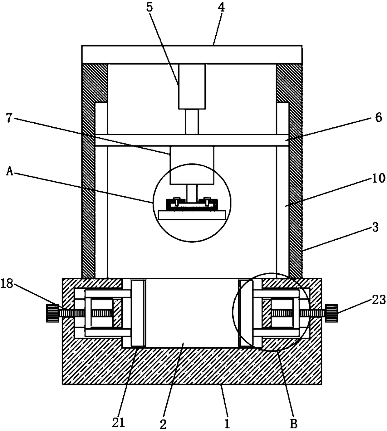
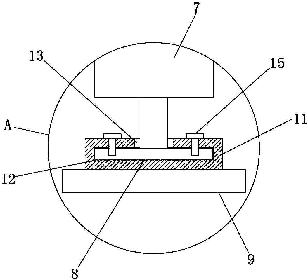
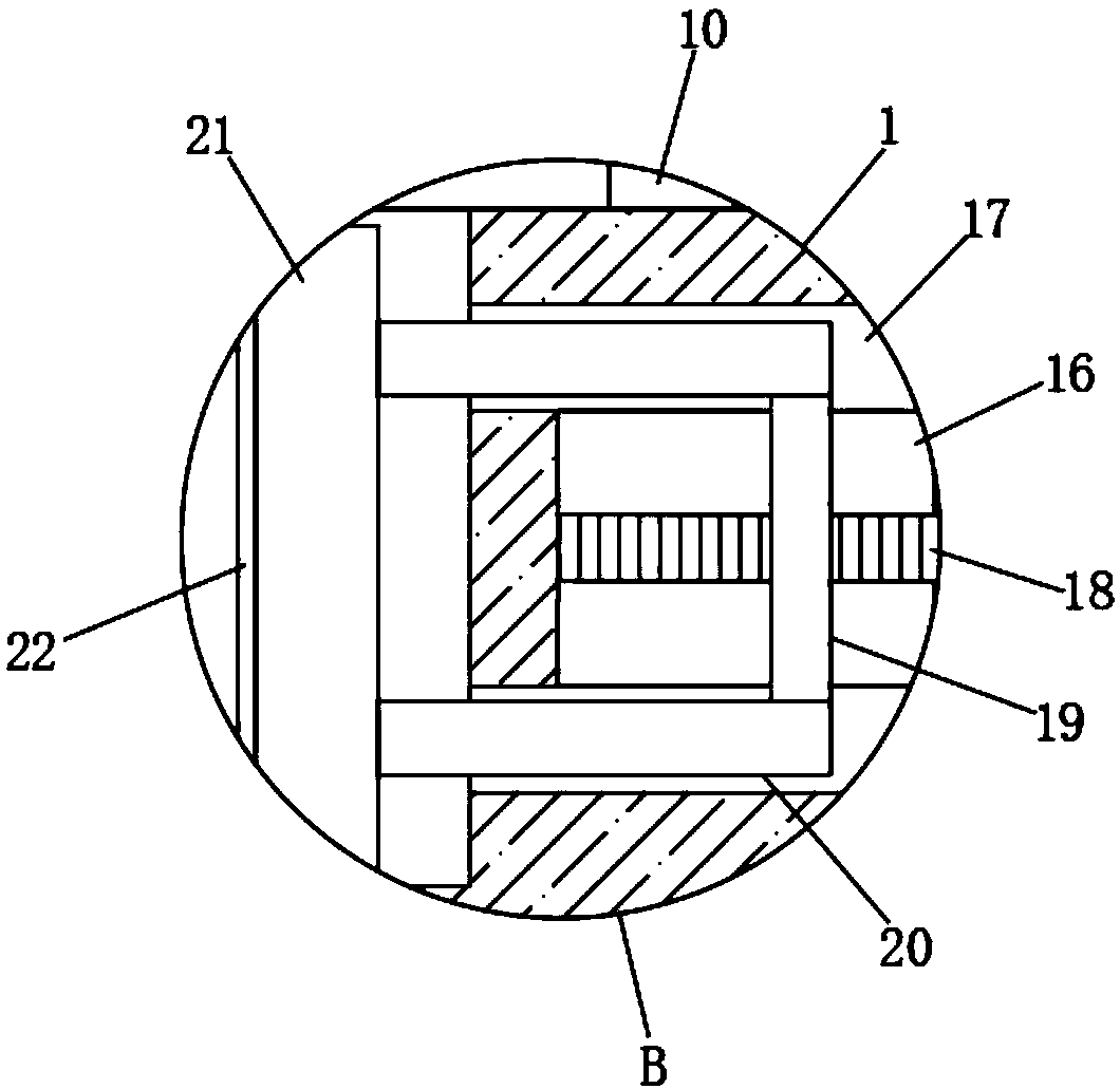
[0022] refer to Figure 1-4 , a mechanical processing polishing device, comprising a base 1, the upper side wall of the base 1 is provided with a placement groove 2, the upper side wall of the base 1 is fixedly connected with two mutually symmetrical support plates 3, the two support plates 3 The first fixed plate 4 is fixedly connected to the upper side wall, the cylinder 5 is fixedly connected to the lower side wall of the first fixed plate 4, the output end of the cylinder 5 is fixedly connected to the connecting plate 6, and the opposite sides of the two supporting plates 3 The first chute 10 is provided on the wall, both ends of the connecting plate 6 extend int...


PUM


Abstract

The invention discloses a machining and polishing device. The machining and polishing device comprises a base, a placement groove is formed in the side wall of the upper end of the base, the side wallof the upper end of the base is fixedly connected with two mutually symmetric support plates, a first fixing plate is fixedly connected to the side walls of the upper ends of the two support plates,an air cylinder is fixedly connected to the side wall of the lower end of the first fixing plate, a connecting plate is fixedly connected to an output end of the air cylinder, and a driving motor is fixedly connected to the side wall of the lower end of the connecting plate. Mechanical workpieces to be polished and machined can be stably and firmly clamped, the situation that the mechanical workpieces slide and are damaged since the mechanical workpieces are not clamped stably and firmly in the process of polishing and machining is avoided, the polishing height can be adjusted according to themechanical workpieces different in size, the polishing size and precision can be adjusted according to different polishing requirements, the polishing and machining precision is improved, and convenience is provided for replacing polishing discs different in specification; the machining and polishing device is very easy to assemble and disassemble, and the polishing efficiency is improved.

Description

technical field [0001] The invention relates to the technical field of machining equipment, in particular to a machining polishing device. Background technique [0002] Machining refers to the process of changing the shape or performance of a workpiece through a mechanical device. According to the difference in processing methods, it can be divided into cutting processing and pressure processing. With the improvement of economic level and the development of scientific and technological level, various industries The degree of refinement of the industry is also improving. In the machining parts industry, the use of special work platforms to machine parts reflects the degree of refinement. The machining process is the step in the manufacturing and processing of workpieces or parts. , The process of directly changing the shape, size and surface quality of the blank to make it a part is called the machining process. [0003] The existing mechanical processing polishing device ha...

Claims


Application Information

Patent Timeline
Patent Type & Authority Applications(China)
IPC IPC(8): B24B29/02B24B41/06B24B47/12B24B47/22
CPCB24B29/02B24B41/06B24B47/12B24B47/22
Inventor 蔡同俊
Owner 盐城市同俊精密机械制造有限公司
Why Eureka
Try Eureka