Quick interception liquid pneumatic jet nozzle

A pneumatic nozzle and liquid technology, which is applied in the field of rapid interception of liquid pneumatic nozzles, can solve the problems of insufficient production capacity, easy wear on the surface, poor sealing effect, etc., so as to improve the sealing effect and reduce walking. Path, simple structure effect

Active Publication Date: 2019-01-18
NINGBO WEIRUI PRECISION MACHINERY
View PDF10 Cites 0 Cited by
  • Summary
  • Abstract
  • Description
  • Claims
  • Application Information

AI Technical Summary

Problems solved by technology

[0002] With the continuous rise of the automobile industry market, coupled with the current electrical appliances market and the increasing demand for plastic products in daily life, the production equipment (injection molding equipment) of plastic products is constantly improving every year, but it still cannot meet the market's demand for various plastic products. Demand, especially for LSR injection molding products, is in short supply. With the continuous increase of equipment, the production capacity has not been clearly reflected. The main reason for this phenomenon is that the core structural components of existing injection molding equipment (cut-off nozzles) are still traditional structures. Under the condition of speed and pressure, it will cause glue leakage and a large number of defective products, which is purely low-pressure and low-speed production
In addition, because the valve needle is located in the flow channel and reciprocates in the flow channel to open and close the gate, and the valve needle is in reciprocating contact with the molten resin in the flow channel for a long time, the surface is prone to wear and tear, which may cause poor sealing effect. it is good

Method used


Image

  • Quick interception liquid pneumatic jet nozzle
  • Quick interception liquid pneumatic jet nozzle
  • Quick interception liquid pneumatic jet nozzle

Examples


Embodiment Construction

[0030] The present invention will be described in detail below in conjunction with the accompanying drawings and specific embodiments, wherein the schematic embodiments and descriptions are only used to explain the present invention, but not as improper limitations to the present invention.

[0031] It should be noted that, in the case of no conflict, the embodiments in the present application and the features in the embodiments can be combined with each other. The present invention will be described in detail below with reference to the accompanying drawings and examples.

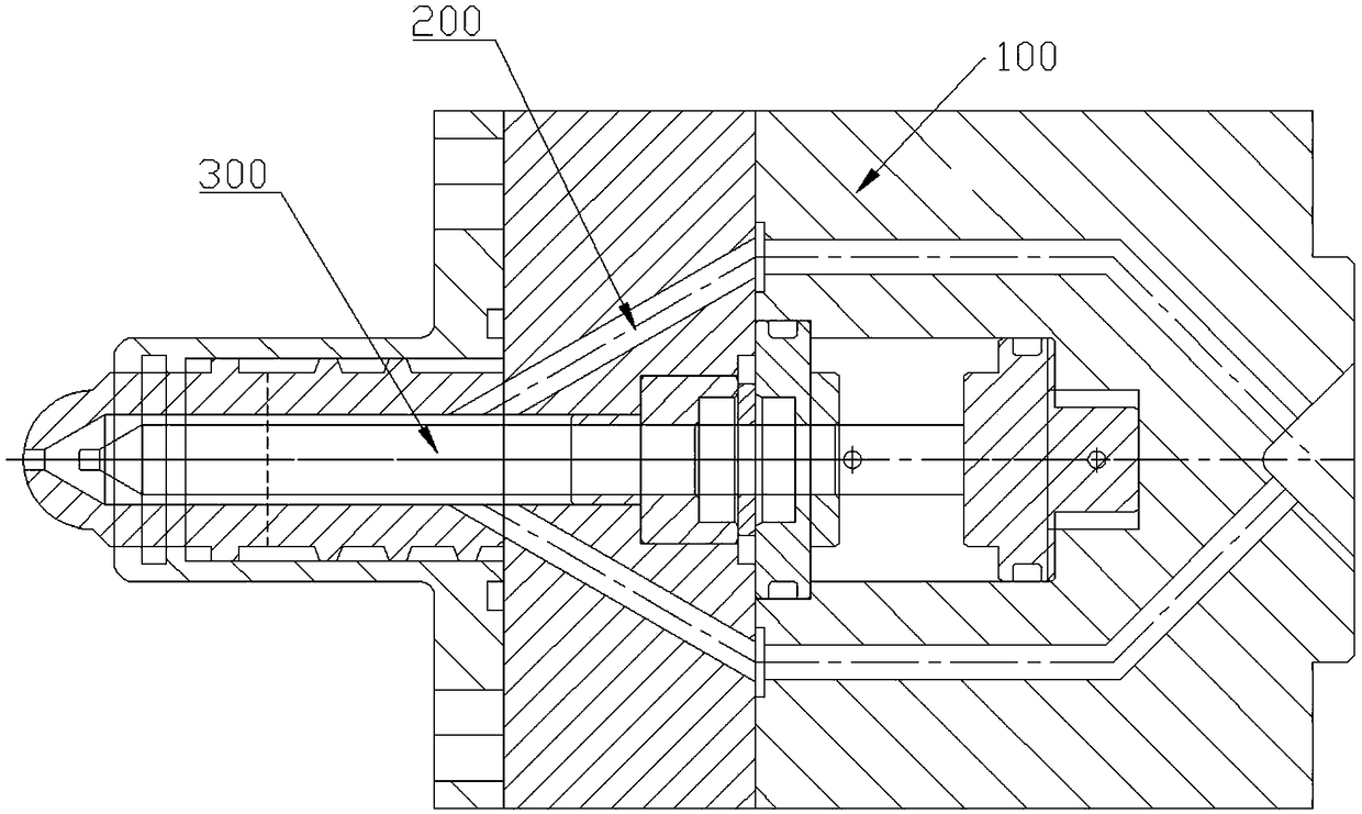
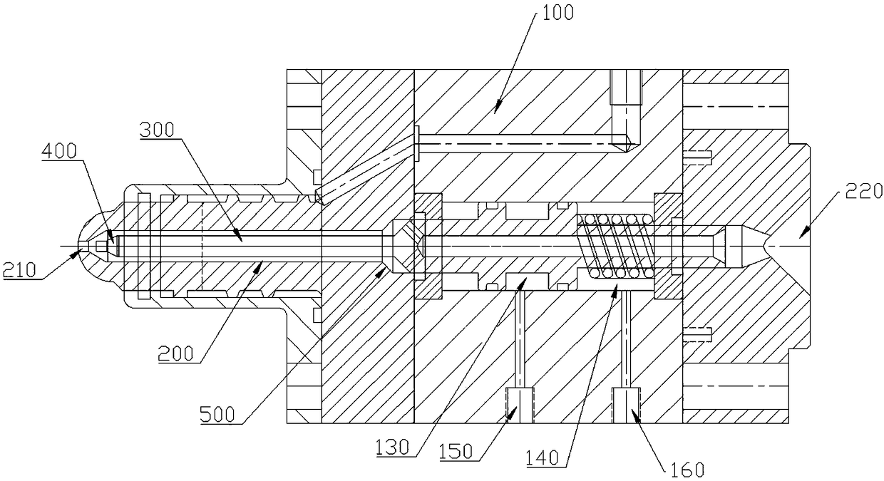
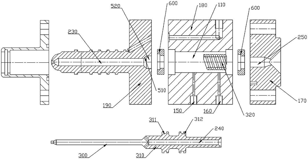
[0032] The fast shut-off liquid pneumatic nozzle includes a nozzle body, the nozzle body is provided with a rubber channel and a valve needle, the front end of the rubber channel is provided with a rubber outlet, and the rear end is provided with a rubber inlet; The rubber sealing part, the first sealing part seals the rubber material outlet when the valve needle moves along the rubber material channel to ...


PUM


Abstract

The invention discloses a quick interception liquid pneumatic jet nozzle. The quick interception liquid pneumatic jet nozzle comprises a jet nozzle body, wherein an adhesive material passage and a valve needle are arranged in the jet nozzle body, the front end of the adhesive material passage is provided with an adhesive material outlet, and the rear end is provided with an adhesive material inlet; the front end of the valve needle is provided with an adhesive sealing part, and the first adhesive sealing part seals the adhesive material outlet when the valve needle moves towards the adhesive material outlet along the adhesive material passage; and a second adhesive sealing part is arranged inside the adhesive material passage, the second adhesive material part comprises an adhesive sealingsurface, and the adhesive sealing surface cuts off the adhesive material passage while the first adhesive sealing part seals the adhesive material outlet. The quick interception liquid pneumatic jetnozzle is simple in structure; by changing the traditional design concept, the novel effective jet nozzle is provided and used for jetting an adhesive material, and the jet nozzle is effective and stable in an application process; and by synchronously sealing an adhesive contact surface by the double adhesive material parts, the adhesive leakage can be doubly prevented, and the requirement of jetting the adhesive material at a high speed and high pressure can be met.

Description

technical field [0001] The invention relates to a mold device for injection molding, in particular to a fast-cut liquid pneumatic nozzle. Background technique [0002] With the continuous rise of the automobile industry market, coupled with the current electrical appliances market and the increasing demand for plastic products in daily life, the production equipment (injection molding equipment) of plastic products is constantly improving every year, but it still cannot meet the market's demand for various plastic products. Demand, especially for LSR injection molding products, is in short supply. With the continuous increase of equipment, the production capacity has not been clearly reflected. The main reason for this phenomenon is that the core structural components of existing injection molding equipment (cut-off nozzles) are still traditional structures. Under the condition of speed and pressure, it will cause glue leakage and a large number of defective products, which ...

Claims


Application Information

Patent Timeline
IPC IPC(8): B29C45/23
CPCB29C45/231
Inventor 赵本根
Owner NINGBO WEIRUI PRECISION MACHINERY
Why Eureka
Try Eureka