Using method of linkage type discharging valve

A blanking valve and linkage technology, applied in the field of medium conveying control, can solve the problems of increasing production and installation costs, increasing material accumulation, poor stability, etc., to achieve the effect of enhancing sealing performance, avoiding material accumulation and strong stability

Active Publication Date: 2019-01-18
CHANGSHA UNIVERSITY OF SCIENCE AND TECHNOLOGY
View PDF7 Cites 0 Cited by
  • Summary
  • Abstract
  • Description
  • Claims
  • Application Information

AI Technical Summary

Problems solved by technology

[0004] 1. The blanking valve of the prior art has a single function or each function is independent, which often occupies a large space and increases the cost of production and installation
[0005] 2. The blanking valve of the prior art is limited by the installation space, and it is difficult to realize the function of uniform mixing and stirring, so that the mixing degree of each sample material in the final molding is different
[0006] 3. The blanking valve of the prior art, in the process of unloading, is difficult to realize the function of accurately controlling the amount of blanking, and cannot meet the needs of modern blanking
[0007] 4. The blanking valve of the prior art, after the installation is completed and the structure is fixed, it is difficult to realize non-disassembly adjustment, resulting in uneven blanking and difficulty in adapting to different working conditions
[0008] 5. For the blanking valve in the prior art, the external driving device is used as an auxiliary part, which is fixed or has high cost or poor stability
[0009] 6. In the blanking valve of the prior art, materials are easy to accumulate on the valve plate, and the sealing performance is not enough. After using parts such as sealing rings, the sealing performance is improved, but the material accumulation is further aggravated

Method used


Image

  • Using method of linkage type discharging valve
  • Using method of linkage type discharging valve
  • Using method of linkage type discharging valve

Examples


Embodiment Construction

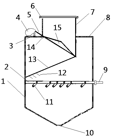
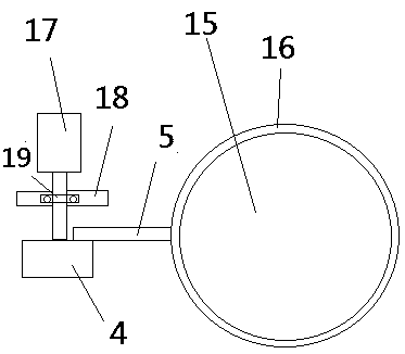
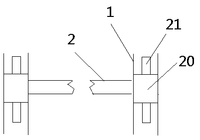
[0043] As shown in the figure: a method of using a linkage type blanking valve. The blanking valve includes a cylinder, a partition, a spring, a wheel, a pole, a flange, a straight cylinder, a cylinder shoulder, a cylinder, a discharge port, Blades, combs, telescopic rods, fulcrums, conical discs, damping rings, servo motors, brackets, hoops, rotating rings, protrusions; their use methods include working methods and adjustment methods;

[0044] As shown in the figure: a cylinder shoulder is set above the cylinder, the middle of the cylinder shoulder extends upwards to form a straight cylinder, a flange is arranged above the straight cylinder, a part of the straight cylinder extends downward from the horizontal line of the cylinder shoulder to form an inclined opening and closing opening, and the conical disk is closed Or to open the opening and closing opening, a pole is arranged on the upper left of the conical disc, and the fulcrum is set at the junction of the cylinder shoul...


PUM


Abstract

The invention discloses a using method of a linkage type discharging valve. The working method comprises the following steps that 1, a conical disc and a partition plate are in the closed state, a servo motor is made to rotate, a wheel disc is driven to rotate, the small end of the wheel disc is lifted, a supporting rod is driven to rotate, and the conical disc is opened; meanwhile, the conical disc pushes two stretchable rods to rotate along an annular groove for storage; 2, after a certain quantity of materials are discharged, the servo motor rotates reversely, the conical disc is closed, meanwhile, the conical disc pulls the two stretchable rods to rotate along the annular groove, broaches are used for carding the materials, and after the conical disc is closed, the stretchable rods continue to rotate by a certain distance under the effect of inertia; 3, a cylinder moves, a piston rod is driven to move, vane plates are driven by a short connecting rod to be opened, and discharging is controlled according to the opening time and the opening degree of the vane plates; 4, the cylinder moves reversely to close the vane plates.

Description

technical field [0001] The invention relates to the related field of media conveying control, in particular to a method for using a linkage type blanking valve. Background technique [0002] In the process of conveying various materials, the unloading valve and the blanking valve are commonly used terminal links; the materials involved are different, including minerals, sand, grain, etc. For various materials, the blanking valve needs are different. [0003] In actual use, the existing blanking valves and discharge valves have the following problems: [0004] 1. The blanking valve of the prior art has a single function or each function is independent, which often occupies a large space and increases production and installation costs. [0005] 2. The blanking valve of the prior art is limited by the installation space, and it is difficult to realize the function of uniform mixing and stirring, so that the mixing degree of each sample material in the final molding is differe...

Claims


Application Information

Patent Timeline
IPC IPC(8): B65G65/48
CPCB65G65/48
Inventor 杜荣华孟灿谌海霞何云邱刚
Owner CHANGSHA UNIVERSITY OF SCIENCE AND TECHNOLOGY
Why Eureka
Try Eureka