A method of using a double-layer combined flap valve

A flap valve, double-layer technology, applied in the direction of transportation and packaging, conveyor objects, etc., can solve the problems of increasing production and installation costs, increasing material accumulation, single function, etc., to enhance sealing performance, avoid material accumulation, control precise effect

Active Publication Date: 2020-07-21
CHANGSHA UNIVERSITY OF SCIENCE AND TECHNOLOGY
View PDF7 Cites 0 Cited by
  • Summary
  • Abstract
  • Description
  • Claims
  • Application Information

AI Technical Summary

Problems solved by technology

[0004] 1. The flap valve of the prior art has a single function or each function is independent, which often occupies a large space and increases the cost of production and installation
[0005] 2. Due to the limitation of the installation space, it is difficult for the flap valve of the prior art to realize the function of uniform mixing and stirring, so that the mixing degree of each sample material in the final molding is different.
[0006] 3. The flap valve of the prior art is difficult to realize the function of precisely controlling the amount of material to be discharged during the discharge process, and cannot meet the requirements of modern material discharge.
[0007] 4. With the flap valve of the prior art, after the installation is completed and the structure is fixed, it is difficult to realize non-disassembly adjustment, resulting in uneven blanking and difficulty in adapting to different working conditions
[0008] 5. In the flap valve of the prior art, an external driving device is used as an auxiliary part, which is fixed or has high cost or poor stability
[0009] 6. In the flap valve of the prior art, materials are easy to accumulate on the valve plate, and the sealing performance is not enough. After using parts such as sealing rings, the sealing performance is improved, but the material accumulation is further aggravated
[0010] 7. The flap valve in the prior art has a single function, and it is difficult to realize the combined function

Method used


Image

  • A method of using a double-layer combined flap valve
  • A method of using a double-layer combined flap valve
  • A method of using a double-layer combined flap valve

Examples


Embodiment Construction

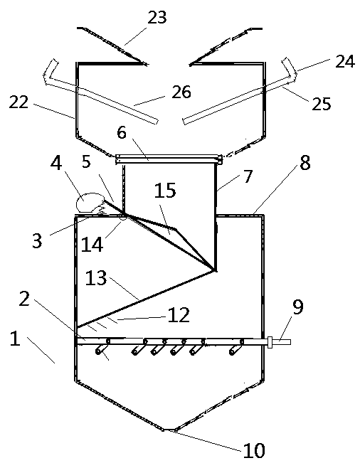
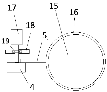
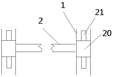
[0046] As shown in the figure: a method of using a double-layer combined flap valve, including a first blanking valve and a second blanking valve, the first blanking valve is located on the upper floor, and the second blanking valve is located on the lower floor; the first blanking valve is located on the lower floor; The blanking valve includes an upper cylinder, a funnel, a bend, a lever, a left flap, and a right flap; through the bend, the lever can be controlled to rotate, thereby driving the left flap and the right flap to rotate, and then open or close The first blanking valve is provided with a funnel above the upper cylinder, which is convenient for receiving materials; the second blanking valve includes a lower cylinder, a partition, a spring, a wheel, a pole, a flange, a straight cylinder , cylinder shoulder, cylinder, discharge port, leaf plate, comb teeth, telescopic rod, fulcrum, conical disk, damping ring, servo motor, bracket, hoop, rotating ring, protrusion; the...


PUM


Abstract

The invention relates to a method for using a double-layer combination flap valve. The working method includes the following steps that firstly, left and right flapping plates, a conical plate and a partition plate are in a closed state in the initial state, when materials fall through a funnel, bends are rotated to open the left and right flapping plates, and thus the materials pass through a first falling valve; secondly, the left and right flapping plates are closed, a servo motor is rotated to drive a wheel disc to rotate, the small head of the wheel disc is uplifted to drive a supportingrod to rotate, thus a conical disc is opened, and meanwhile two telescopic rods are pushed to rotate along a ring groove to receive by the conical disc; thirdly, after a certain amount of falling, theservo motor is rotated reversely, the conical disc is closed, meanwhile the conical disc pulls the two telescopic rods to rotate along the ring groove, comb teeth on the ring groove comb the materials, and when the conical disc is closed, the telescopic rods continue to rotate for a section of distance under the action of inertia; fourthly, an air cylinder is moved to drive a piston rod to move,vane plates are opened through short connecting rods, and falling is controlled according to the opening degree and opening time of the vane plates; and fifthly, the air cylinder is moved reversely toclose the vane plates.

Description

technical field [0001] The invention relates to the related field of media conveying control, in particular to a method for using a double-layer combined flap valve. Background technique [0002] In the process of conveying various materials, flap valves, unloading valves, and unloading valves are commonly used terminal links; the materials involved are different, including minerals, sand, grain, etc., for various Materials and blanking requirements are different. [0003] In actual use, the existing flap valves, blanking valves, and discharge valves have the following problems: [0004] 1. The flap valve of the prior art has a single function or each function is independent, which often occupies a large space and increases production and installation costs. [0005] 2. Due to the limitation of the installation space, it is difficult for the flap valve of the prior art to realize the functions of uniform mixing and stirring, so that the mixing degree of each sample materia...

Claims


Application Information

Patent Timeline
Patent Type & Authority Patents(China)
IPC IPC(8): B65G47/248
CPCB65G47/248
Inventor 杜荣华邱刚谌海霞何云孟灿
Owner CHANGSHA UNIVERSITY OF SCIENCE AND TECHNOLOGY
Why Eureka
Try Eureka