Energy-saving protecting device applicable to opening and closing of window of historical building

A technology for historical buildings and protection devices, applied in the direction of buildings, building structures, building fastening devices, etc., can solve the problems of time-consuming and labor-intensive, wooden windows cannot be let, not in line with energy saving and environmental protection, etc., to ensure stability. Effect

Pending Publication Date: 2018-09-14
NANYANG INST OF TECH
View PDF0 Cites 1 Cited by
  • Summary
  • Abstract
  • Description
  • Claims
  • Application Information

AI Technical Summary

Problems solved by technology

[0003] Since most of the historical buildings are made of wooden structures, from the perspective of protection, the wooden windows cannot be opened and closed by visitors. For large historical buildings, a large number of windows must be opened and closed by relevant management personnel. It is time-consumi...

Method used


Image

  • Energy-saving protecting device applicable to opening and closing of window of historical building
  • Energy-saving protecting device applicable to opening and closing of window of historical building
  • Energy-saving protecting device applicable to opening and closing of window of historical building

Examples


Embodiment 1

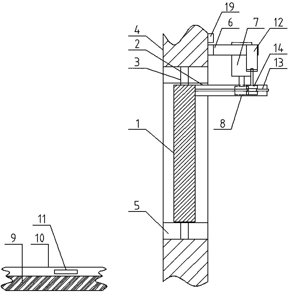
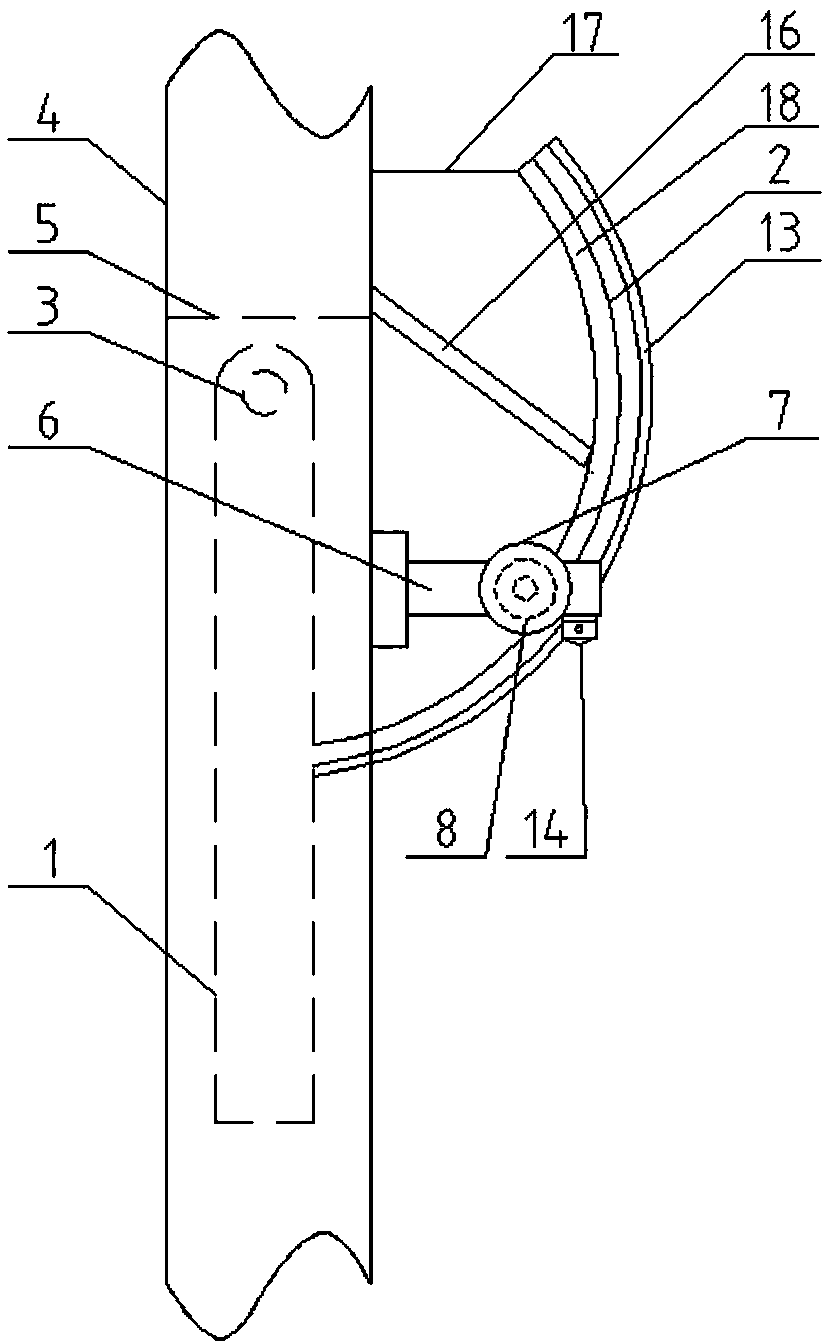
[0039] Such as figure 1 , 2As shown in and 5-9: an energy-saving protection device for opening and closing windows of historical buildings, including an arc-shaped rack 2 arranged outside the shaft of the window sash 1, and an opening and closing mechanism arranged on the wall at the 3 places of the shaft of the window sash 1 , the locking mechanism 16 arranged on the wall 4 and matched with the opening and closing mechanism, the power supply mechanism arranged on the ground 9 of the historic building, and the locking mechanism 16 arranged on the wall and used to control the opening and closing mechanism , the locking mechanism 16 and the control mechanism 19 of the power supply mechanism;

[0040] The opening and closing mechanism includes a motor support 6 arranged on the outside of the wall body 4 and above the window frame 5, a driving motor 7 arranged on the motor support 6, arranged on the output shaft of the driving motor 7 and connected with The driving gear 8 matche...

Embodiment 2

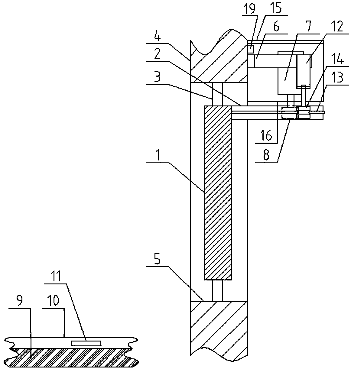
[0050] Such as Figure 3-4 As shown: the difference from Embodiment 1 is that a rain shelter 15 is provided outside the wall 4 and above the motor support 6 .

[0051] The bottom edge of the canopy 15 is provided with an enclosure 16 for surrounding the drive motor 7 .

[0052] The drive motor 7 is a brushed DC motor.

[0053] The arc-shaped rack 2 is made of aluminum.

[0054] The storage battery 11 is a lithium battery.

[0055] The end of the curved rack 2 is provided with an elastic rope 17 matched with the window sash.

[0056] In this embodiment, in order to prevent the driving motor from being wet in rainy days, a rain shelter is provided on the outside of the wall and above the motor support. The enclosure of the drive motor; the drive motor used can also be a stepper motor, and the elastic rope used can ensure that the arc-shaped rack and the drive gear are closely attached to ensure the stability of the device's operation.

[0057] The use method of the present ...


PUM


Abstract

The invention discloses an energy-saving protecting device applicable to opening and closing of a window of a historical building. The device comprises an arc-shaped rack which is arranged at the outer side of a rotating shaft of a window sash, an opening and closing mechanism which is arranged on a wall body at the rotating shaft of the window sash, a locking mechanism which is arranged on the wall body and fits the opening and closing mechanism, a power supplying mechanism which is arranged on a floor of the historical building, and a control mechanism which is arranged on the wall body andis used for controlling the opening and closing mechanism, the locking mechanism and the power supplying mechanism. With the adoption of the device, a wooden window of the historical building can be automatically regularly opened and closed, and the opening state can be locked; and in addition, power can be automatically generated as a visitor walks in the building, so that the independent power supply demand is met, and the energy is greatly saved.

Description

technical field [0001] The invention belongs to the technical field of historical building protection, and in particular relates to an energy-saving protection device for opening and closing windows of historical buildings. Background technique [0002] Historic buildings refer to buildings and structures that have a certain protection value and can reflect historical features and local characteristics as determined by the city and county people's governments. They are different from cultural relics protection units and buildings and structures that cannot be moved. Buildings with cultural relic value, historical buildings are buildings with certain architectural value. [0003] Since most of the historical buildings are made of wooden structures, from the perspective of protection, the wooden windows cannot be opened and closed by visitors. For large historical buildings, a large number of windows must be opened and closed by relevant management personnel. It is time-consu...

Claims


Application Information

Patent Timeline
IPC IPC(8): E05F15/619E05C17/38E05C19/00E05F15/79E05F15/71
CPCE05C17/38E05C19/003E05F15/619E05F15/71E05F15/79E05Y2900/148
Inventor 何航贺一明
Owner NANYANG INST OF TECH
Why Eureka
Try Eureka