A Dynamic Light Source System for Laser Speckle Dissipation

A light source system and speckle dissipation technology, applied in the field of laser speckle dissipation light source systems, can solve problems such as difficulty in finding intermediate specifications

Active Publication Date: 2020-10-23
SICHUAN CHANGHONG ELECTRIC CO LTD
View PDF5 Cites 0 Cited by
  • Summary
  • Abstract
  • Description
  • Claims
  • Application Information

AI Technical Summary

Problems solved by technology

[0005] In a three-color laser TV, since the speckle conditions of the three primary colors are different, setting the same speckle-eliminating device in the optical path will have different effects for each color, and it is difficult to find suitable technical specifications to meet the speckle-eliminating requirements of each color at the same time. , there is a situation where it is difficult to find a suitable intermediate specification

Method used


Image

  • A Dynamic Light Source System for Laser Speckle Dissipation
  • A Dynamic Light Source System for Laser Speckle Dissipation
  • A Dynamic Light Source System for Laser Speckle Dissipation

Examples


Embodiment 1

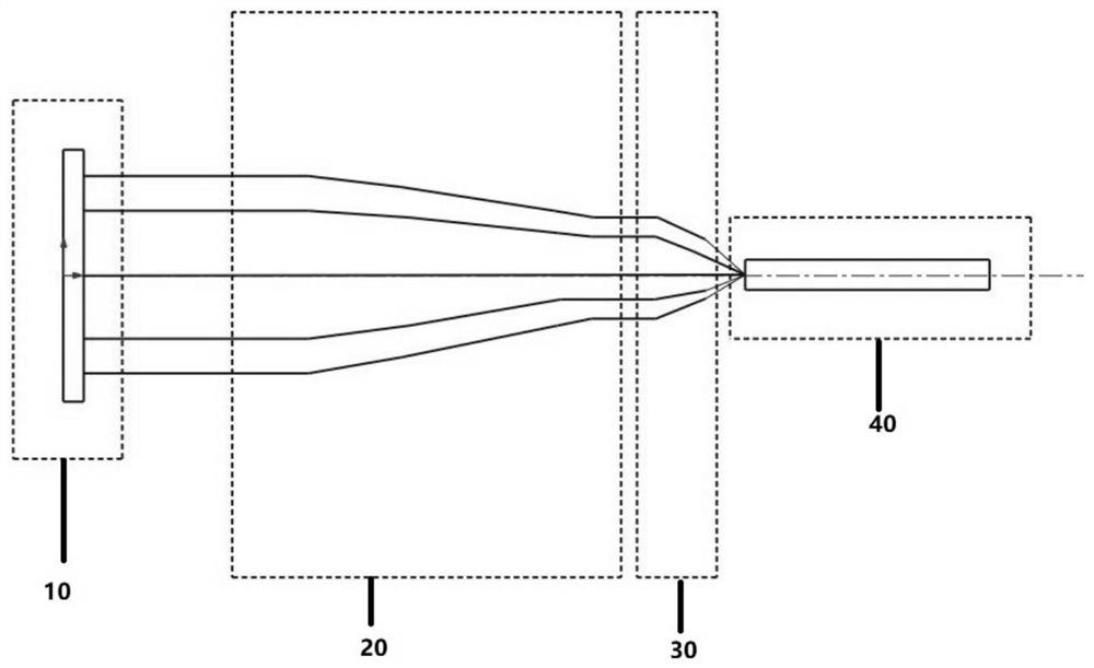
[0054] Such as figure 1 As shown, a dynamic light source system for laser speckle dissipation includes a light source assembly 10, a beam reduction system 20 for combining the laser beams emitted by the light source assembly 10, a focusing assembly 30, and a uniform light device 40; The focusing assembly 30 is disposed between the beam shrinking system 20 and the light homogenizing device 40 , and the focusing assembly 30 is used to focus the laser beam passing through the beam shrinking system 20 and enter the light uniforming device 40 for light homogenization.

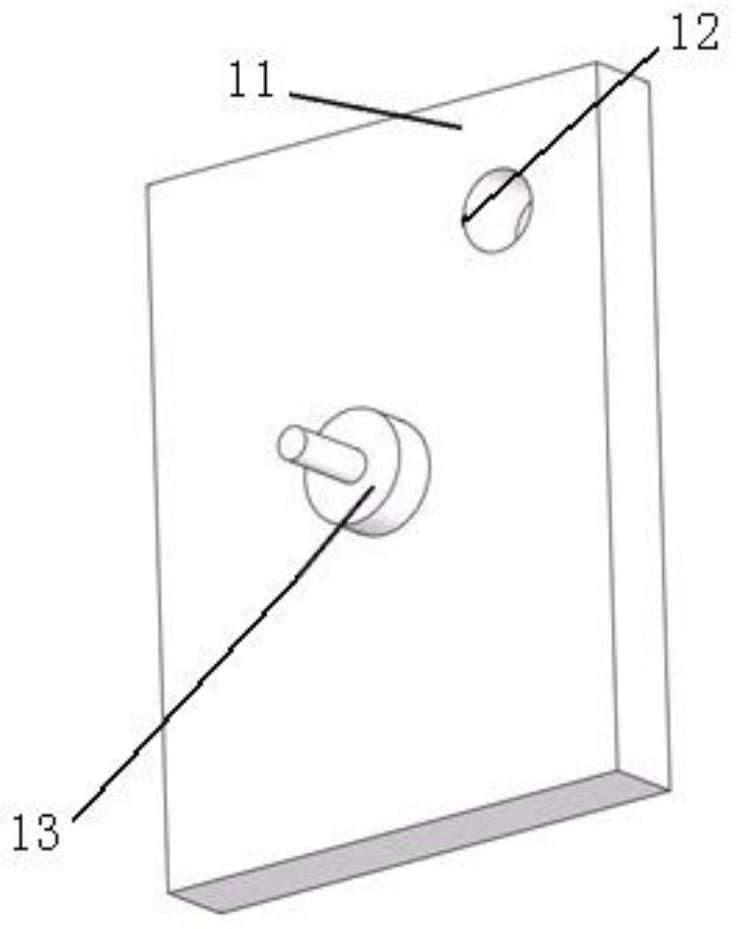
[0055] The light source assembly 10 includes a laser fixing substrate 11, a laser 14, a vibrating assembly 13 and an alignment assembly 15. The laser fixing substrate 11 is provided with a plurality of through laser fixing holes 12, and each laser fixing hole 12 is fixed with a Lasers 14 , each laser 14 is connected with a collimating component 15 , and the vibrating component 13 is connected on the laser fixing sub...

Embodiment 2

[0063] Such as figure 1 As shown, this embodiment provides an array arrangement of lasers 14 relative to Embodiment 1, so that the structure of the light source assembly 10 is more compact, and the light source assembly 10 is illustrated with reference to image 3 , the laser fixing substrate 11 is provided with several through laser fixing holes 12, each laser fixing hole 12 is fixed with a laser 14, and each laser 14 is connected with a collimation assembly 15, and the vibration assembly 13 is connected to the laser fixing on the substrate 11. The arrangement of the lasers 14 on the laser fixed substrate 11 and the reference direction of the fast axis Image 6 , wherein the wavelength of the laser 14 used is the same, and the requirements for the vibrating component 13 are the same as those in Embodiment 1, and will not be repeated here.

Embodiment 3

[0065] In this embodiment, the vibration component 13 is a plurality of vibration micro components 131, the number of the vibration micro components 131 is equal to the number of lasers 14, each vibration micro component 131 is connected to the corresponding laser 14, and the laser 14 The direction of the slow axis of the laser is perpendicular to the direction of the fast axis of the laser 14 . The vibration micro-component 131 is designed separately for each laser 14, so that the vibration mode of each laser 14 is independent, and the specific schematic diagram refers to Figure 7 , the diagram shows the array arrangement of the lasers 14, and the fast axis direction of the lasers 14 refers to Image 6 , the vibration amplitude of the vibration microcomponent 131 is independently designed with respect to the central wavelength of the laser 14 it controls.

[0066] The central wavelengths of the lasers 14 used in this embodiment can be the same or different, and the light so...


PUM


Abstract

The invention discloses a dynamic light source system for eliminating laser speckles, which relates to the technical field of laser display. The dynamic light source system comprises a light source assembly, a beam shrinking system, a focusing assembly and a light homogenizing device, wherein the beam shrinking system is used for combining laser emitted from the light source assembly; the focusingassembly is arranged between the beam reducing system and the light homogenizing device, and the focusing assembly is used for focusing the laser beam passing through the beam shrinking system to enter the light homogenizing device for light homogenization; the light source assembly comprises a laser device fixing substrate, laser devices, a vibration assembly and collimating assemblies, a plurality of laser device fixing holes are formed in the laser device fixing substrate in a penetrated manner, the laser devices are each fixed in one of the laser device fixing holes, each laser device isconnected with one collimating assembly, and the vibration assembly is connected on the laser device fixing substrate.

Description

technical field [0001] The invention relates to the technical field of laser display, in particular to a dynamic light source system for laser speckle dissipation. Background technique [0002] Due to its good monochromaticity, laser has an incomparable advantage in the color of the display field compared to other light sources, and its lifespan of tens of thousands of hours has also greatly improved the market competitiveness of laser TVs. At present, the laser display market is in a period of rapid development, and the technology is changing rapidly. At present, the mainstream product is still a laser TV with a monochrome laser plus phosphor solution. However, with the development of laser technology, two-color and three-color laser TVs have become The future direction of housing development. [0003] Whether it is a monochrome, two-color or three-color laser TV, the extremely narrow spectral line width of the laser will introduce a long coherence length (or coherence tim...

Claims


Application Information

Patent Timeline
Patent Type & Authority Patents(China)
IPC IPC(8): G02B27/48G02B27/10G02B27/30
CPCG02B27/1006G02B27/30G02B27/48
Inventor 梁其鹏何龙姜银磊
Owner SICHUAN CHANGHONG ELECTRIC CO LTD
Why Eureka
Try Eureka