Complete picture fusion method, device and system

A fusion method and technology of a fusion device, applied in closed-circuit television systems, components of television systems, image data processing, etc., can solve problems such as poor picture effects, and achieve the effect of solving poor picture effects

Pending Publication Date: 2019-01-01
王芮
View PDF4 Cites 2 Cited by
  • Summary
  • Abstract
  • Description
  • Claims
  • Application Information

AI Technical Summary

Problems solved by technology

[0004] In view of this, the present invention provides a complete picture fusion method, device and system to solve the problem of poor spliced ​​picture effect due to partial overlap when multiple small pictures are spliced ​​into a complete picture

Method used


Image

  • Complete picture fusion method, device and system
  • Complete picture fusion method, device and system
  • Complete picture fusion method, device and system

Examples


Embodiment 1

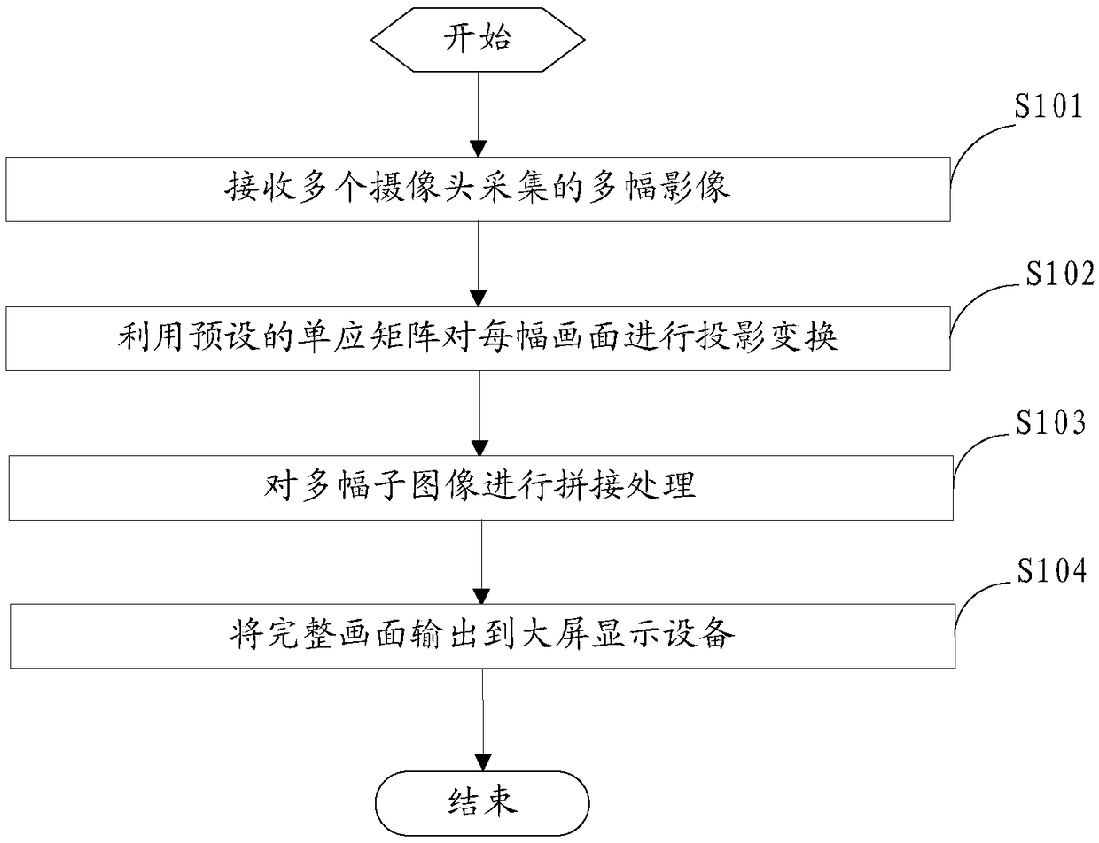
[0041] figure 1 It is a flow chart of steps of an embodiment of a complete picture fusion method provided by the present invention.

[0042] refer to figure 1 As shown, the complete picture fusion method provided in this embodiment specifically includes the following steps:

[0043] S101: Receive multiple images collected by multiple cameras.

[0044] Since the scene to be monitored is relatively large, and the area covered by each camera is limited, the premise of this application is to set up multiple cameras. Output the captured and output images to obtain multiple images.

[0045] In view of the shape and size of the required monitoring scene, multiple cameras can be arranged in a two-dimensional matrix or in a ring, so that multiple images can be obtained in a corresponding two-dimensional matrix or in a ring.

[0046] S102: Perform projection transformation on each frame by using a preset homography matrix.

[0047] The homography matrix is ​​obtained by calculating...

Embodiment 2

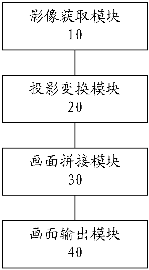
[0058] figure 2 It is a structural block diagram of an embodiment of a complete picture fusion device provided by the present invention.

[0059] refer to figure 2 As shown, the complete picture fusion device provided in this embodiment specifically includes an image acquisition module 10 , a projection transformation module 20 , a picture splicing module 30 and a picture output module 40 .

[0060] The image acquisition module is used for receiving multiple images collected by multiple cameras.

[0061] Since the scene to be monitored is relatively large, and the area covered by each camera is limited, the premise of this application is to set up multiple cameras. Output the captured and output images to obtain multiple images.

[0062] In view of the shape and size of the required monitoring scene, multiple cameras can be arranged in a two-dimensional matrix or in a ring, so that multiple images can be obtained in a corresponding two-dimensional matrix or in a ring.

[0...

Embodiment 3

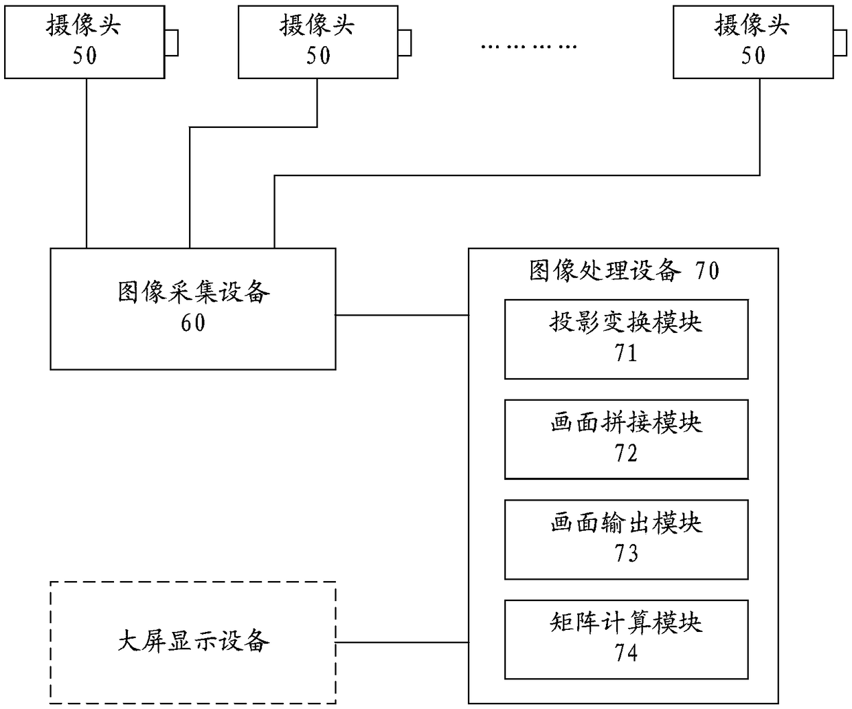
[0074] image 3 It is a schematic structural diagram of an embodiment of a complete picture fusion system provided by the present invention.

[0075] refer to image 3 As shown, the complete picture fusion system provided by this embodiment includes a plurality of cameras 50, video acquisition equipment 60 and image processing equipment 70, and the video acquisition equipment is connected with each camera and image processing equipment respectively, and the image processing equipment is also provided with useful The signal output port for outputting a complete picture.

[0076] Multiple cameras are arranged according to preset rules to completely cover the scene to be monitored. The arrangement can be arranged in a two-dimensional matrix or in a ring according to different monitoring requirements. Each camera can obtain a partial image of the scene to be monitored, and output it to the image acquisition device through its signal output terminal.

[0077] The image acquisiti...


PUM


Abstract

The embodiment of the invention provides a complete picture fusion method, device and system. The complete picture fusion method specifically comprises the steps of receiving multiple images collectedby multiple cameras; performing projection transformation on each image by using a preset homography matrix to obtain multiple sub-pictures to be spliced; splicing the multiple sub-pictures to obtaina complete picture; and outputting the complete picture to large-screen display equipment. In the invention, projection transformation is performed on the images obtained by each camera through the homography matrix, and then splicing processing is carried out to obtain the complete picture, thereby being capable of effectively removing overlapping parts, and thus solving a problem of poor picture effect caused by the partial overlap existing in small pictures when the complete picture is spliced.

Description

technical field [0001] The invention relates to the technical field of monitoring, in particular to a complete picture fusion method, device and system. Background technique [0002] In many situations, such as large squares, train stations or bus stations, it is necessary to display live images in a large area so as to monitor the crowd and ensure the safety of the above occasions. Since a single camera can only capture a small area of ​​view, when a large area needs to be displayed, multiple cameras are required to collect images of different areas, and then display all the images through the display device. [0003] In order to ensure better coverage, the cameras need to be partially overlapped. When the images collected by multiple cameras are stitched together, there will be overlapped images, resulting in poor spliced ​​images, resulting in poor monitoring effects. Contents of the invention [0004] In view of this, the present invention provides a complete picture ...

Claims


Application Information

Patent Timeline
Patent Type & Authority Applications(China)
IPC IPC(8): H04N7/18H04N5/265G06T3/00G06T3/40G06T5/50
CPCH04N5/265H04N7/181G06T3/00G06T3/4038G06T5/50G06T2207/20221
Inventor 周柏贾贾群林李欣陈莉王芮陈振杰张煜
Owner 王芮
Why Eureka
Try Eureka