Binocular fundus camera
A camera, binocular technology, used in ophthalmoscope, equipment for testing eyes, medical science, etc.
- Summary
- Abstract
- Description
- Claims
- Application Information
AI Technical Summary
Problems solved by technology
Method used
Image
Examples
Embodiment 1
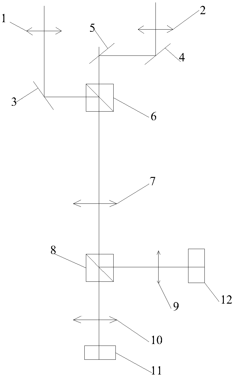
[0031] Such as figure 1 As shown, the present embodiment provides a binocular fundus camera, including a left eyepiece 2, a right eyepiece 1, an illumination system and a photography system arranged in the camera body of the fundus camera. The illumination system is arranged on the light source of the fundus camera and Between the left eyepiece 2 and the right eyepiece 1, and the lighting system is used to divide the light emitted by the light source into two paths respectively through the left eyepiece 2 and the right eyepiece 1 to enter the eyes; the photography system includes optical components and camera components, optical components Set between the camera assembly and the two eyepieces, the light reflected by the fundus of the eye to be inspected passes through the left eyepiece 2 and the right eyepiece 1, and then passes through the optical assembly to the camera assembly for imaging.
[0032]The optical assembly includes a first reflective mirror A3, a second reflecti...
Embodiment 2
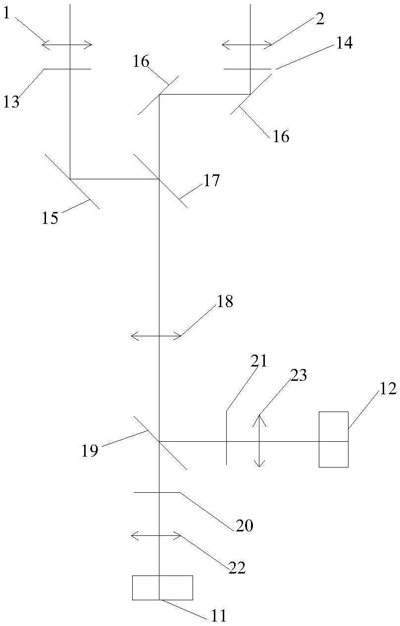
[0036] Such as figure 2 As shown, this embodiment provides a binocular fundus camera. On the basis of Embodiment 1, the optical components used in the binocular fundus camera of this embodiment are different from those in Embodiment 1, specifically:
[0037] The optical assembly includes a first polarizer 13, a second polarizer 14, a first mirror B15, a second mirror B16, a first beam splitter 17, a second beam splitter 19, a first objective lens B18, a second objective lens B22, The third objective lens B23, the first polarizing plate 20 and the second polarizing plate 21, the camera assembly includes a left camera 11 and a right camera 12, the inner side of the right eyepiece 1 is sequentially provided with the first polarizing plate 13, the first polarizing plate along the light reflection direction. Mirror B15, the first beam splitter 17, the first objective B18, the second beam splitter 19, the second analyzer 21 and the third objective B23, the rear side of the third ob...
Embodiment 3
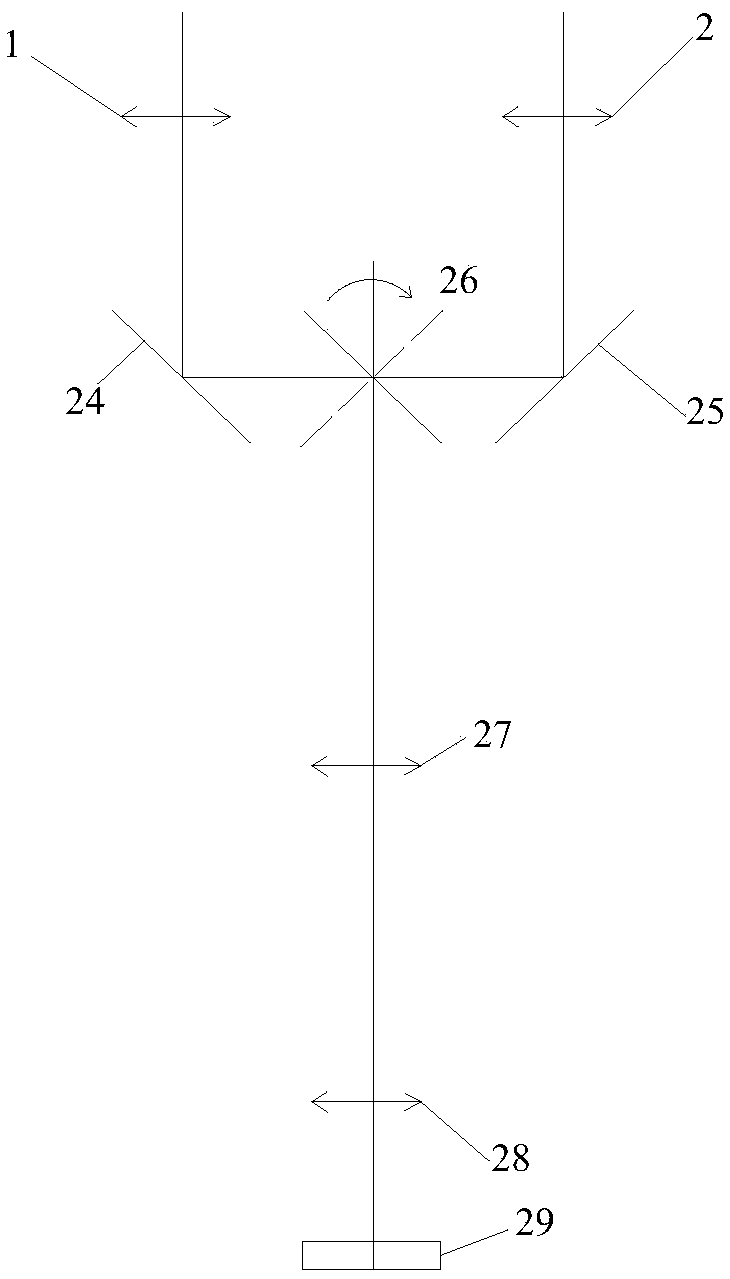
[0042] Such as image 3 As shown, this embodiment provides a binocular fundus camera. On the basis of Embodiment 1, the optical components used in the binocular fundus camera of this embodiment are different from those in Embodiment 1, specifically:
[0043] The optical assembly includes the first mirror C24, the second mirror C25, the rotating mirror 26, the first objective lens C27 and the second objective lens C28, the camera assembly is a camera 29, and the inner side of the right eyepiece 1 and the left eyepiece 2 are respectively provided with the first A mirror C24 and a second mirror C25, a rotating mirror 26 is arranged between the first mirror C24 and the second mirror C25, and a first objective lens C27 and a second objective lens C28 are successively arranged at the light-emitting end of the rotating mirror 26, The rear side of the second objective lens C28 is the camera 29 .
[0044] During use, after the fundus is illuminated, the light reflected from the fundus...
PUM
 Abstract
Description
Claims
Application Information
 - R&D
- Intellectual Property
- Life Sciences
- Materials
- Tech Scout
- Unparalleled Data Quality
- Higher Quality Content
- 60% Fewer Hallucinations
Browse by: Latest US Patents, China's latest patents, Technical Efficacy Thesaurus, Application Domain, Technology Topic, Popular Technical Reports.
© 2025 PatSnap. All rights reserved.Legal|Privacy policy|Modern Slavery Act Transparency Statement|Sitemap|About US| Contact US: help@patsnap.com


