Yarn clamping device of spinning machine

A spinning machine and yarn clamping technology, applied in textiles and papermaking, etc., can solve problems such as production troubles, unadjustable yarn transmission direction, fixed height, etc., and achieve flexible use, wide application range, and change of yarn transmission angle Effect

Inactive Publication Date: 2019-02-01
湖北德永盛纺织有限公司
View PDF5 Cites 2 Cited by
  • Summary
  • Abstract
  • Description
  • Claims
  • Application Information

AI Technical Summary

Problems solved by technology

[0002] Spinning machine yarn guide usually needs to use the yarn clamping device, and the yarn passes between the yarn clamping discs. Most of the existing yarn clamping discs are fixed, and the yarn transmission direction is basically not adjustable. It is necessary to dismantle the yarn clamping disc and reposition and install it, which brings troubles to the actual production, and the height of the yarn transmission is basically fixed, so the applicable spinning situation has certain limitations

Method used


Image

  • Yarn clamping device of spinning machine
  • Yarn clamping device of spinning machine
  • Yarn clamping device of spinning machine

Examples


Embodiment Construction

[0033] Embodiments of the present invention are described in detail below, examples of which are shown in the drawings, wherein the same or similar reference numerals designate the same or similar elements or elements having the same or similar functions throughout. The embodiments described below by referring to the figures are exemplary only for explaining the present invention and should not be construed as limiting the present invention.

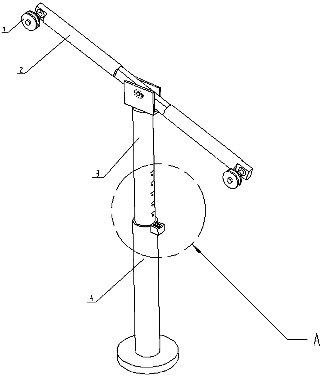
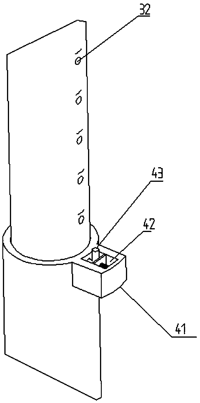
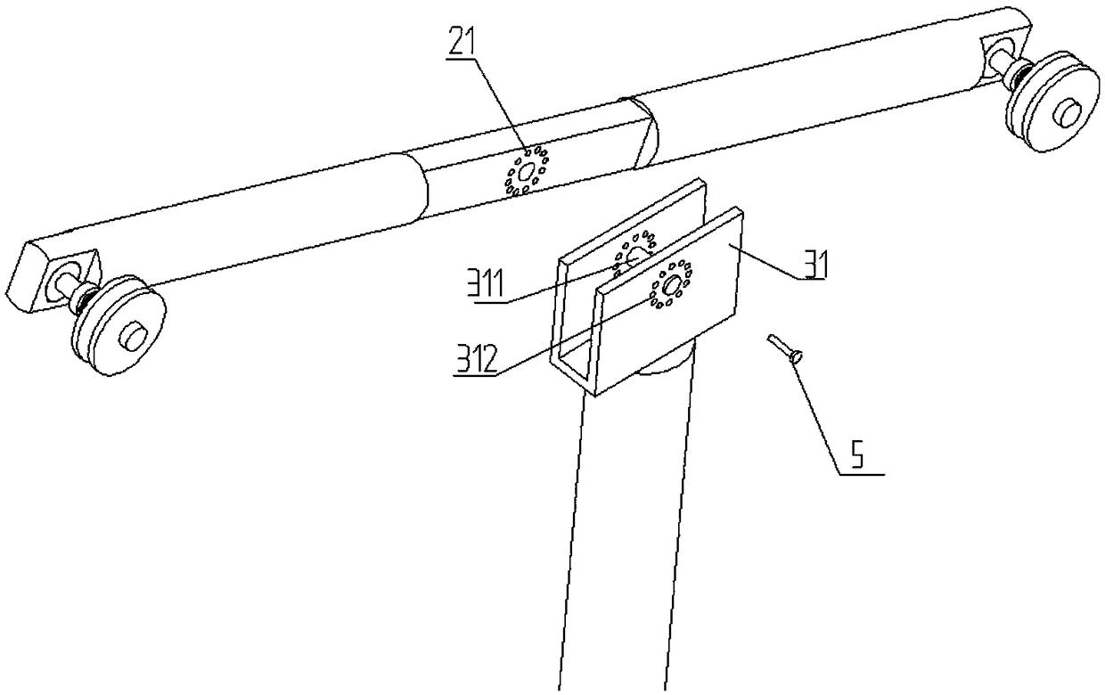
[0034] Such as figure 1 As shown, the yarn clamping device of the spinning machine in this embodiment includes a cylindrical support 4, a lifting rod 3, a cross bar 2 and a yarn clamping disc 1. The lifting rod 3 is sleeved on the upper end of the cylindrical support 4 and can move up and down. , the two yarn clamping discs 1 are connected to the same side of the two ends of the cross bar 2 through shaft rotation, the two yarn clamping discs 1 can rotate, and the yarn is wound on the two yarn clamping discs 1, and the yarn clamping disc ...


PUM


Abstract

The invention relates to a yarn clamping device of a spinning machine. The yarn clamping device comprises a cylinder support, a lifting rod sleeved with the cylinder support, a transverse rod rotationally connected with the lifting rod, and yarn clamping plates rotationally matched with the same sides of the two ends of the transverse rod. A multi-gear inserted connection structure for adjusting the inclination angle of the transverse rod is arranged at the matched position of the transverse rod and the lifting rod. By means of the yarn clamping device, the yarn conveying angle of the yarn clamping plates can be adjusted, the height of the yarn clamping plates can also be adjusted, and the yarn clamping device is suitable for various spinning conditions.

Description

technical field [0001] The invention relates to the field of spinning machines, in particular to a yarn clamping device for a spinning machine. Background technique [0002] Spinning machine yarn guide usually needs to use the yarn clamping device, and the yarn passes between the clamping discs. Most of the existing clamping discs are fixed, and the yarn transmission direction is basically not adjustable. When the yarn transmission direction needs to be adjusted It is necessary to remove the yarn clamping disc and reposition and install it, which brings troubles to the actual production, and the height of the yarn transmission is basically fixed, so the applicable spinning situation has certain limitations. Contents of the invention [0003] The invention provides a yarn clamping device for a spinning machine, which can flexibly adjust the height and angle of the yarn clamping, and is more versatile than the traditional yarn clamping device in various spinning environments...

Claims


Application Information

Patent Timeline
Patent Type & Authority Applications(China)
IPC IPC(8): D01H13/04
Inventor 章爱武陈保峰游建平陈锋
Owner 湖北德永盛纺织有限公司
Why Eureka
Try Eureka