A design method for wind-resistant system of pipeline suspension cable spanning structure

A technology that spans structures and design methods, applied in suspension bridges, design optimization/simulation, computer-aided design, etc., can solve problems such as limitations, inability to provide lateral and vertical stiffness, high engineering costs, etc., to improve lateral and vertical The effect of stiffness

Active Publication Date: 2020-02-04
BC P INC CHINA NAT PETROLEUM CORP +2
View PDF5 Cites 0 Cited by
  • Summary
  • Abstract
  • Description
  • Claims
  • Application Information

AI Technical Summary

Problems solved by technology

In the past engineering design, the wind-resistant cable system with a large angle with the horizontal plane was generally adopted or the bridge deck structure with high rigidity was adopted. However, due to the influence of the terrain of the canyon, the conventional wind-resistant cable layout is extremely difficult, and the installation of wind-resistant cables is extremely difficult. However, it cannot provide sufficient lateral and vertical rigidity, and at the same time, the bridge deck structure with higher stiffness will bring higher engineering costs

Method used


Image

  • A design method for wind-resistant system of pipeline suspension cable spanning structure
  • A design method for wind-resistant system of pipeline suspension cable spanning structure
  • A design method for wind-resistant system of pipeline suspension cable spanning structure

Examples


Embodiment Construction

[0044] In order to make the object, technical solution and advantages of the present invention clearer, the present invention will be further described in detail below in conjunction with the accompanying drawings and embodiments. It should be understood that the specific embodiments described here are only used to explain the present invention, not to limit the present invention.

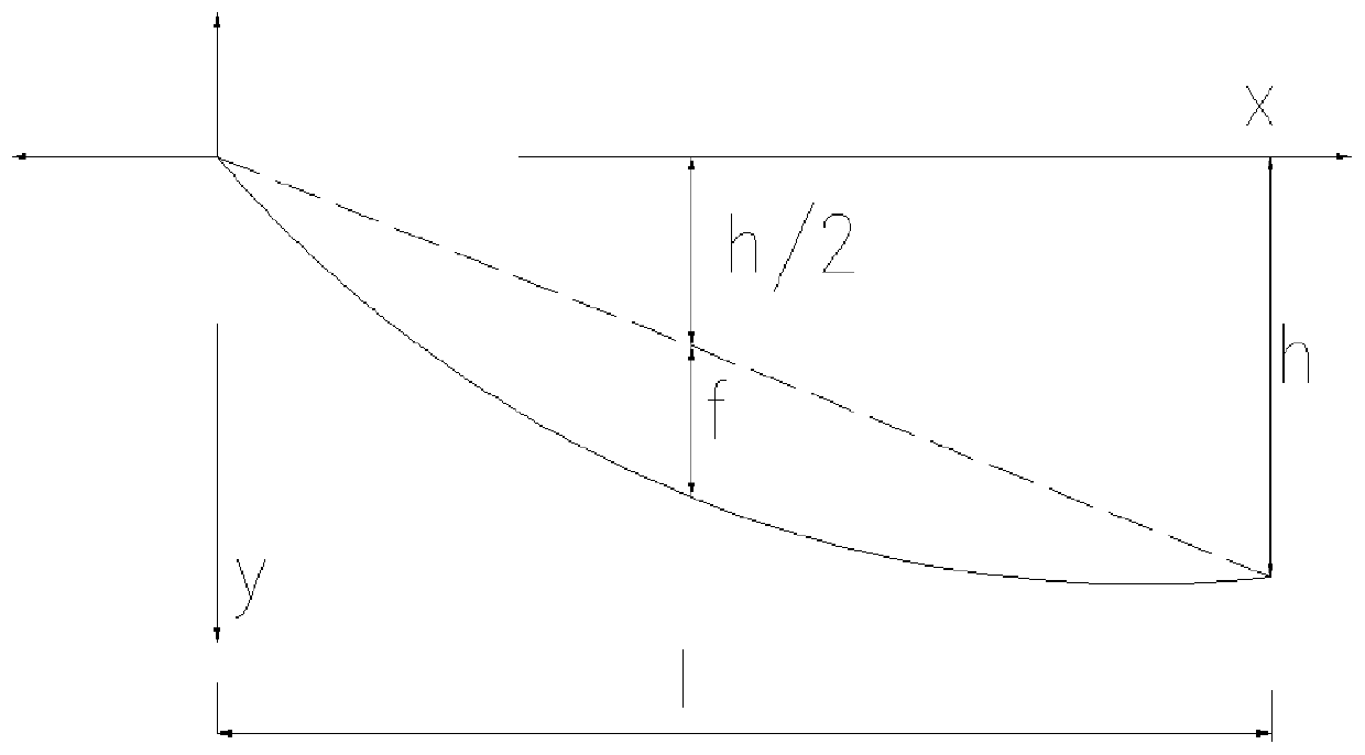
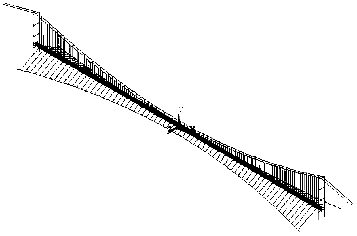
[0045] A pipeline suspension cable spanning structure wind resistance system, such as Figure 5 , 6 As shown, there are two pipeline suspension cables spanning the bridge tower 12, and the pipeline suspension cables span the bridge tower 12 and are fixed on the pier 13, and a cap 14 is provided below the pier 13. The two main cables 11 respectively pass through two pipelines and are suspended across the top of the bridge tower 12 and are arranged in a parabolic shape in the vertical direction. The cable hanger has a pipeline suspension cable to span the bridge deck 15 . The two ends of the pipel...


PUM


Abstract

The invention relates to a design method for a wind resistance system of a pipeline suspended cable crossing structure. The design method comprises the steps that step 1, a curve element of a horizontal wind resistance cable and a conjugate cable is drawn up; step 2, a finite element model and vibration performance of the finite element model are built; step 3, model numbers of the horizontal windresistance cable and the conjugate cable are preliminary drawn up; step 4, the pretension force of the horizontal wind resistance cable and the conjugate cable is determined; step 5, scale models ofthe wind resistance system of the pipeline suspended cable crossing structure are assembled and a wind tunnel test is carried out to verify the wind resistance safety performance of the scale models under the ultimate state; and step 6, the final cable force of a main cable, the horizontal wind resistance cable and the conjugate cable are calculated, a main cable anchoring pier, a conjugate cableanchoring pier and a wind cable anchoring pier meeting the requirements are designed. According to the design method for the wind resistance system of the pipeline suspended cable crossing structure,the aims that the pipeline suspended cable crossing structure resists a horizontal wind load and wind load lift force, and improves lateral and vertical stiffness of the structure are realized, and anovel mode is provided in order to solve the wind resistance safety problem of the pipeline crossing structure under the canyon terrian condition.

Description

technical field [0001] The invention relates to a design method for a wind resistance system of a pipeline suspension cable spanning structure, which belongs to the field of oil and gas pipeline spanning engineering design. Background technique [0002] Pipeline suspension cable spanning engineering is one of the most commonly used methods for long-distance oil and gas pipelines to cross rivers. The suspension cable spanning structure has the characteristics of strong spanning capacity, low structural stiffness, and low damping. It is extremely sensitive to wind loads, especially in canyon river areas. Influenced by canyon wind, structural wind-induced safety is one of the most concerned aspects of pipeline spanning projects. In the past engineering design, the wind-resistant cable system with a large angle with the horizontal plane was generally adopted or the bridge deck structure with high rigidity was adopted. However, due to the influence of the terrain of the canyon, t...

Claims


Application Information

Patent Timeline
Patent Type & Authority Patents(China)
IPC IPC(8): E01D11/02E01D18/00E01D19/14E01D19/16
CPCE01D11/02E01D18/00E01D19/14E01D19/16G06F30/13G06F30/23G06F2119/06
Inventor 左雷彬马晓成李国辉任文明詹胜文王丽李金玲陈晓晖邵强
Owner BC P INC CHINA NAT PETROLEUM CORP
Why Eureka
Try Eureka