Infrared confocal lens

An infrared confocal and lens technology, applied in the field of infrared confocal lens, can solve the problems of insufficient lightness of the finished product, high production cost, and low relative illuminance, and achieve the effects of low production cost, good infrared confocal, and low temperature drift

Pending Publication Date: 2019-02-12
UNION OPTECH
View PDF0 Cites 1 Cited by
  • Summary
  • Abstract
  • Description
  • Claims
  • Application Information

AI Technical Summary

Problems solved by technology

[0004] The technical problem to be solved by the present invention is to provide an infrared confocal lens for the problems of large defocus, large temperature drift, high production cost, insufficient lightness of the finished product and generally low relative illuminance of the current infrared confocal lens

Method used


Image

  • Infrared confocal lens
  • Infrared confocal lens
  • Infrared confocal lens

Examples


Embodiment Construction

[0053] Embodiments of the present invention will be described in detail below in conjunction with the accompanying drawings.

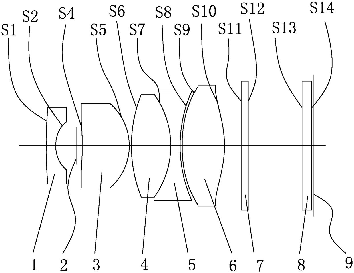
[0054] Such as Figure 1 to Figure 6 As shown, an infrared confocal lens is sequentially provided from the object side to the image side:

[0055] The first lens 1, the first lens 1 has a convex surface facing the object side, and a concave surface facing the image side; the focal length of the first lens 1 is negative;

[0056] aperture 2;

[0057] The second lens 3, the side of the second lens 3 facing the object side is a concave surface, and the side facing the image side is a convex surface; the focal length of the second lens 3 is positive;

[0058] The third lens 4, the side of the third lens 4 towards the object side and the side towards the image side are both convex surfaces; the focal length of the third lens 4 is positive;

[0059] The fourth lens 5, the side of the fourth lens 5 facing the object side and the side facing the image side ...


PUM


Abstract

The invention discloses an infrared confocal lens. A first lens, a diaphragm, a second lens, a third lens, a fourth lens, a fifth lens, an optical filter, protection glass and a light-sensitive chip are sequentially arranged from an object side to an image side, one surface, facing the object side, of the first lens is a convex surface, one surface, facing the image side, of the first lens is a concave surface, the focal length of the first lens is negative, one surface, facing the object side, of the second lens is a concave surface, one surface, facing the image side, of the second lens is aconvex surface, the focal length of the second lens is positive, two surfaces of the third lens are convex surfaces, the focal length of the third lens is positive, one surface, facing the object side, of the fourth lens and one surface, facing the image side, of the fourth lens both are concave surfaces, the focal length of the fourth lens is negative, one surface, facing the object side, of thefifth lens and one surface, facing the image side, of the fifth lens both are convex surfaces, and the focal length of the fifth lens is positive. Each lens employs a concave-convex combination structure, infrared confocality can be achieved very well by selecting a material with appropriate refractivity and reasonably allocating focal power, and meanwhile, small temperature drift is achieved.

Description

【Technical field】 [0001] The invention relates to the technical field of optical lenses, in particular to an infrared confocal lens. 【Background technique】 [0002] Infrared confocal is currently the lens technical specification proposed by the vehicle and security industries, and it is the development trend of the future market. However, most of the current infrared confocal lenses used in vehicles and security systems generally have a large amount of infrared and visible defocus, and it is difficult to achieve high-definition requirements for day and night imaging at the same time. Large, high production cost, the finished product is not light enough, there are vignetting phenomena around, and the relative illuminance is low. [0003] Therefore, the present invention just produces based on above deficiency. 【Content of invention】 [0004] The technical problem to be solved by the present invention is to provide an infrared confocal lens for the problems of large defocu...

Claims


Application Information

Patent Timeline
IPC IPC(8): G02B13/14G02B13/18G02B1/00G02B1/04
CPCG02B13/14G02B13/18G02B1/00G02B1/041
Inventor 罗吉祥肖明志鲍康倩梅纪才刘玉芳
Owner UNION OPTECH
Why Eureka
Try Eureka