Broadcast beam forming method and base station

A broadcast beam and horizontal beam technology, applied in the field of communication, can solve the problems that the horizontal beam width and vertical beam width of the broadcast beam cannot be adjusted dynamically, adjust the beam pointing and beam width, and uneven distribution of users, etc., so as to improve the quality of the broadcast coverage signal Effect

Active Publication Date: 2019-02-12
CHINA MOBILE GRP GUANGDONG CO LTD +1
View PDF3 Cites 15 Cited by
  • Summary
  • Abstract
  • Description
  • Claims
  • Application Information

AI Technical Summary

Problems solved by technology

[0004] However, existing base stations broadcast coverage through fixed horizontal wide beams and vertical narrow beams; by performing broadcast beamforming on the 8T8R antenna, adjusting the horizontal dimension antenna weights of the 8T8R antenna, and generating broadcast beams that conform to the above beam settings, the broadcast beam Fixed, the horizontal beamwidth and vertical beamwidth of the broadcast beam cannot be adjusted dynamically
For example, the existing TDD-LTE (Time Division Duplexing-Long Term Evolution, Time Division Duplex Long Term Evolution) 8T8R base station only supports the coverage of a typical broadcast beam with a horizontal beamwidth of 65 degrees and a vertical beamwidth of 6 degrees.
[0005] In fact, users in the network are usually unevenly distributed, and the range of user hotspots is not fixed; if the existing broadcast beam width cannot be dynamically adjusted for broadcast coverage, it will not be possible to adjust the beam according to changes in user hotspots Pointing and wave width, resulting in reduced broadcast coverage signal quality for user hotspots

Method used


Image

  • Broadcast beam forming method and base station
  • Broadcast beam forming method and base station
  • Broadcast beam forming method and base station

Examples


Embodiment Construction

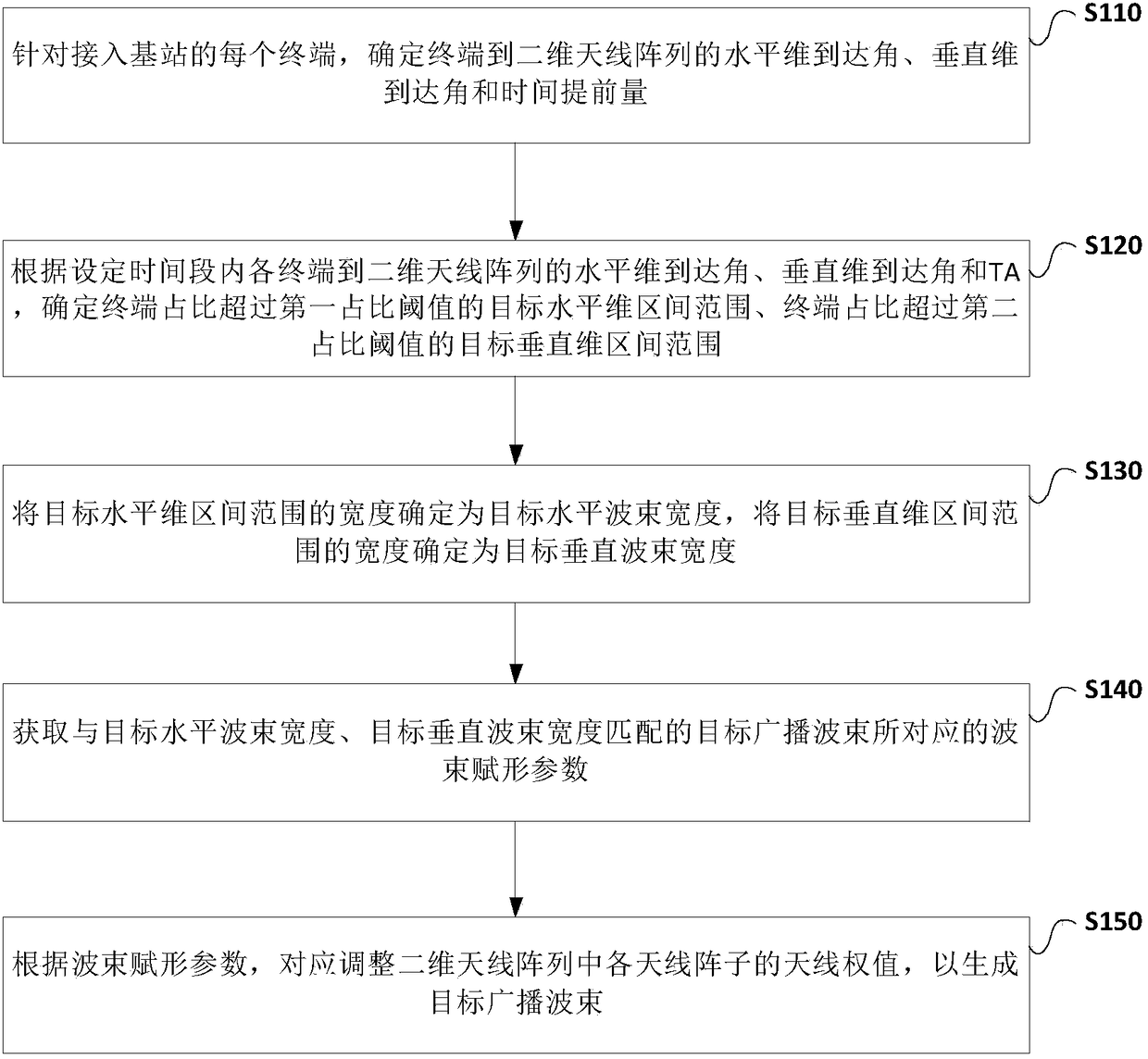
[0035] The technical solutions of the present invention will be clearly and completely described below in conjunction with the accompanying drawings. Apparently, the described embodiments are only some of the embodiments of the present invention, not all of them. Based on the embodiments of the present invention, all other embodiments obtained by persons of ordinary skill in the art without making creative efforts belong to the protection scope of the present invention.

[0036] As used herein, terms such as "module" and "means" are intended to include computer-related entities such as, but not limited to, hardware, firmware, a combination of hardware and software, software, or software in execution. For example, a module may be, but is not limited to being limited to being, a process running on a processor, a processor, an object, an executable, a thread of execution, a program, and / or a computer. For example, both an application running on a computing device and the computin...


PUM


Abstract

The embodiment of the invention provides a broadcast beam forming method, and a base station. The method comprises the following steps: determining horizontal dimension arrival angles, vertical dimension arrival angles and TAs of terminals accessing the base station to a two-dimensional antenna array; determining a target horizontal dimension interval range in which a terminal ratio exceeds a first ratio threshold, and a target vertical dimension interval range in which the terminal ratio exceeds a second ratio threshold according to the horizontal dimension arrival angles, the vertical dimension arrival angles and the TAs of the terminals; determining the width of the target horizontal dimension interval range as a target horizontal beam width, and determining the width of the target vertical dimension interval range as a target vertical beam width; and obtaining a beam forming parameter corresponding to a target broadcast beam matching the target horizontal beam width and the targetvertical beam width to correspondingly adjust antenna weights of antenna arrays to generate a target broadcast beam. By adoption of the method and the base station provided by the embodiment of the invention, the broadcast beam matching a user hotspot can be formed, and the broadcast coverage signal quality of the user hotspot is improved.

Description

technical field [0001] Embodiments of the present invention relate to the field of communication technologies, and in particular, to a broadcast beamforming method and a base station. Background technique [0002] With the continuous development of wireless communication technology, the demand for broadband wireless communication systems continues to increase. It is necessary to make full use of multipath propagation, further open up air space resources, and improve wireless transmission performance. Therefore, the use of smart antennas in wireless broadband networks has gradually become a development trend. [0003] The basic principle of the beamforming of the smart antenna is to use the spatial characteristics of signal transmission to display the beam required for communication by adjusting the weight of the transmitted signal on each vibration source. The existing smart antenna mainly refers to the 8T8R (Transmit, transmit; Receive, receive) antenna; the 8T8R antenna ad...

Claims


Application Information

Patent Timeline
Patent Type & Authority Applications(China)
IPC IPC(8): H04B7/0413H04B7/06
CPCH04B7/0413H04B7/0617
Inventor 许乐飞瞿水华刘华东方琛
Owner CHINA MOBILE GRP GUANGDONG CO LTD
Why Eureka
Try Eureka