Transmitting/receiving device of optical fiber communication

A technology of transmitting and receiving and optical fiber communication, which is applied in the direction of electromagnetic transceivers, etc., can solve the problems of automatic regulation and information disorder, and achieve the effect of intelligent control, ingenious conception, great practical value and promotion value

Inactive Publication Date: 2019-02-12
北海华红信息科技有限公司
View PDF0 Cites 0 Cited by
  • Summary
  • Abstract
  • Description
  • Claims
  • Application Information

AI Technical Summary

Problems solved by technology

[0005] In view of the above situation, in order to overcome the defects of the prior art, the object of the present invention is to provide a new type of optical fiber communication transmitting and receiving device, which effectively solves the problem that the existing optical fiber communication has information disorder and cannot be automatically adjusted when the carrier information is too much

Method used


Image

  • Transmitting/receiving device of optical fiber communication
  • Transmitting/receiving device of optical fiber communication

Examples


Embodiment 1

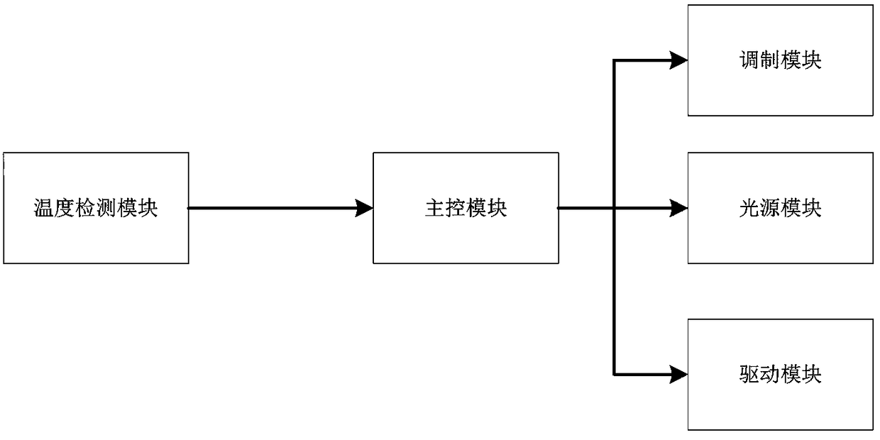
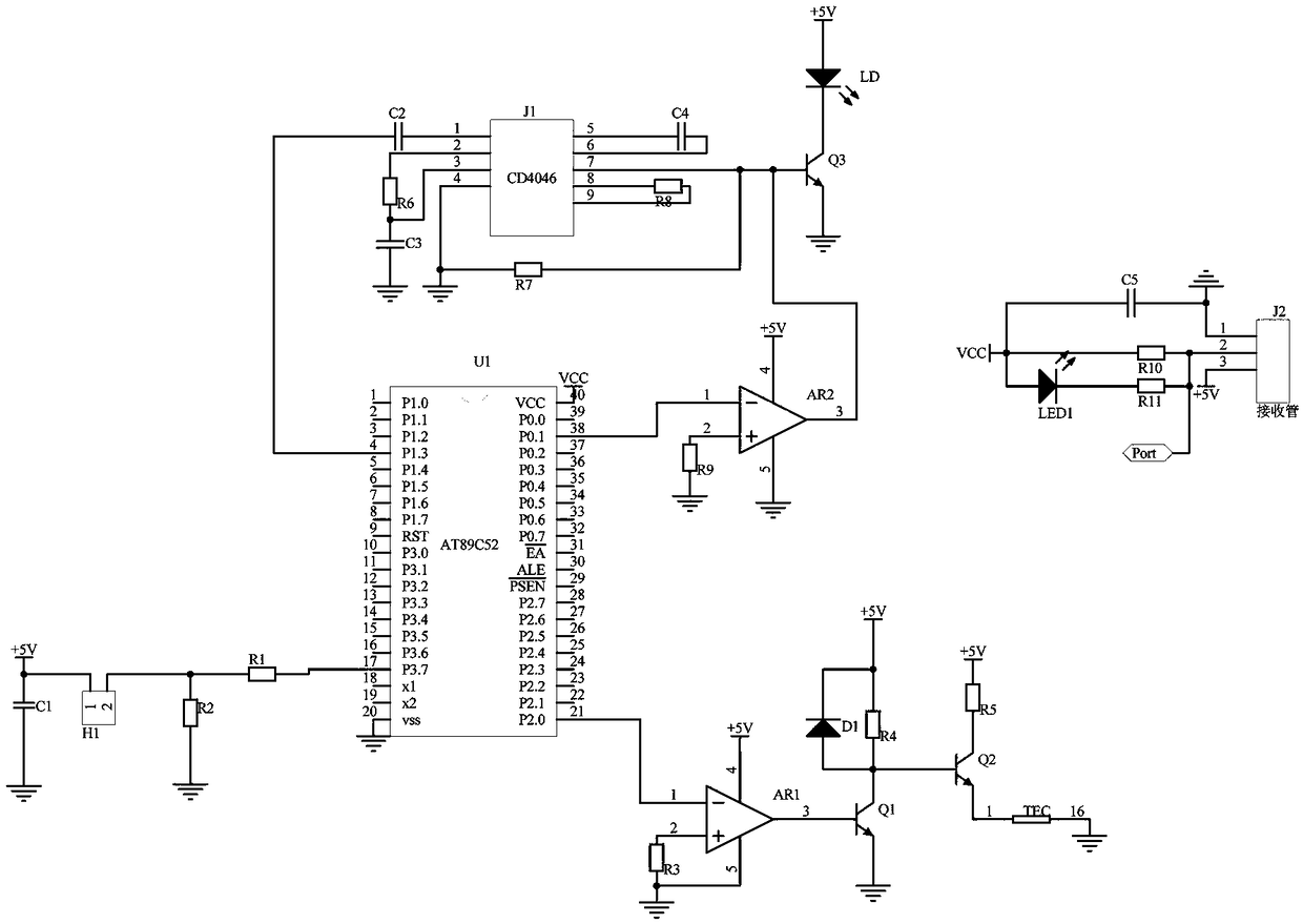
[0020] Embodiment 1, the transmitting device and the receiving device, the transmitting device includes a main control module, a temperature detection module, a modulation module, a light source module and a driving module, the transmitting device is connected to the receiving device through an optical fiber, and the temperature detection module is connected to the main control module, The main control module is connected with the modulating module, the light source module and the driving module; the main control module adopts the single-chip microcomputer U1 of the model AT89C52, and the single-chip microcomputer U1 has high sensitivity and comes with a clock circuit and reset circuit. Pin 38 outputs TTL control light source module signal, its output signal is weak, it needs amplifier AR2 to control, amplifier AR2 provides power supply for it by +5V power supply, amplifier AR2 is a proportional amplifier, the input signal signal of pin 2 of amplifier AR2 is controlled by resist...

Embodiment 2

[0021] Embodiment 2. On the basis of Embodiment 1, the temperature detection module adopts temperature sensor H1 to collect temperature signals, and the power supply +5V is rectified by capacitor C1 into pulsating direct current to provide power for temperature sensor H1. The output signal is an electrical signal, and the voltage And the current is too large to be directly received by the single-chip microcomputer U1. The resistor R2 is connected in parallel with the temperature sensor H1 to divide the voltage, and the resistor R1 and the temperature sensor H1 are connected in series to shunt the current.

Embodiment 3

[0022] Embodiment three, on the basis of embodiment one, described modulation module comprises phase-locked loop chip J1, the pin 1 of phase-locked loop chip J1 connects the pin 4 of single-chip microcomputer U1, the pin 2 of phase-locked loop chip J1 connects One end of resistor R6, the other end of resistor R6 is connected to pin 3 of phase-locked loop chip J1, one end of capacitor C3, the other end of capacitor C3 is grounded, pin 5 of phase-locked loop chip J1 is connected to one end of capacitor C4, capacitor C4 The other end of the resistor R8 is connected to pin 6 of the phase-locked loop chip J1, pin 8 of the phase-locked loop chip J1 is connected to one end of the resistor R8, the other end of the resistor R8 is connected to pin 9 of the phase-locked loop chip J1, and the pin 8 of the phase-locked loop chip J1 Pin 7 is connected to one end of the resistor R7, the other end of the resistor R7 is connected to the pin 4 of the phase-locked loop chip J1, and the pin 4 of t...


PUM


Abstract

The invention relates to a transmitting / receiving device of optical fiber communication. The transmitting / receiving device comprises a transmitting device and a receiving device; the transmitting device comprises a master control module, a temperature detection module, a modulation module, a light source module and a driving module; the transmitting device is connected with the receiving device through the optical fiber; the temperature detection module is connected with the master control module, the master control module is connected with the modulation module, the light source module and the driving module; the problem that the information is disorder and cannot be automatically controlled when the carrier information is excessive at the optical fiber communication is solved; the transmitting / receiving device is ingenious in conception and intelligent in control; a single chip microcomputer U1 in model of AT89C52 is used as a micro controller, various circuit modules of the transmitting device form an integer to realize an automatic control function; the single chip microcomputer U1 in model of AT89C52 controls a phase-locked loop chip J1 in model of CD4046; the information is free from disorder when the carrier information is excessive; the receiving device adopts a receiving tube as a demodulator and is externally connected with an output port; the carrier information canbe well demodulated, and the transmitting / receiving device has great practical value and promotional value.

Description

technical field [0001] The invention relates to the technical field of optical fiber communication, in particular to a transmitting and receiving device for optical fiber communication. Background technique [0002] Communication is realized by electricity, while optical communication is realized by using light as an information carrier. The so-called optical fiber communication is used to transmit and carry information to achieve the purpose of communication. To make light waves a carrier of information, it must be For this, the information is detected from the light wave at the receiving end. [0003] At present, the scope of use of optical fiber communication is increasing, and the information of the carrier is becoming more and more complex. The design of the traditional optical fiber communication transmitting and receiving device gradually presents some problems in the face of the rapid development of the information age. When there is too much carrier information, it ...

Claims


Application Information

Patent Timeline
Patent Type & Authority Applications(China)
IPC IPC(8): H04B10/40
CPCH04B10/40
Inventor 郑如凤
Owner 北海华红信息科技有限公司
Why Eureka
Try Eureka