
System and method for SAP FM demodulation

a frequency modulation and sap channel technology, applied in the field of sap fm demodulation, can solve the problems of unnecessarily complicated process, significant hardware cost, and attempts of current stereo tuners and demodulator units, and achieve the effect of simplifying the demodulation of secondary audio program signals

Inactive Publication Date: 2006-02-28
AVAGO TECH WIRELESS IP SINGAPORE PTE
View PDF16 Cites 11 Cited by
  • Summary
  • Abstract
  • Description
  • Claims
  • Application Information

AI Technical Summary

Benefits of technology

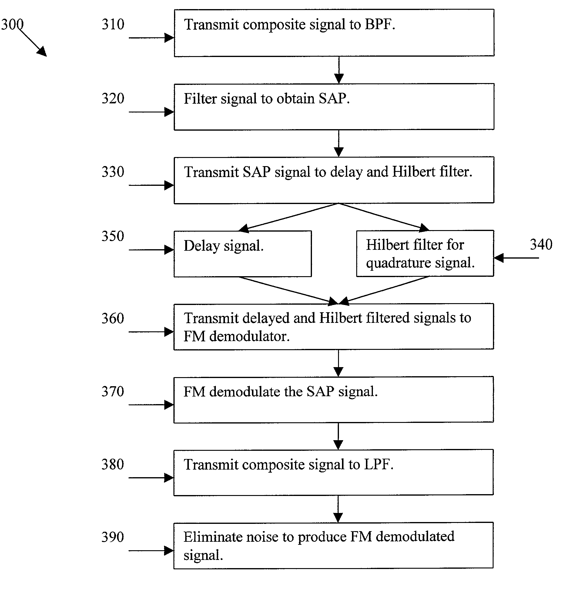
[0012]Certain embodiments of the present invention provides a system and method for SAP FM demodulation. Certain embodiments of the present invention provide a digital FM demodulator that uses a simplified approximation of a digital FM demodulation equation using non-unity delay for simplified demodulation of frequency modulated signals. The system includes a bandpass filter for isolating the SAP signal, a Hilbert filter to produce a copy of the SAP signal phase shifted by 90 degrees, an FM demodulator for demodulating the SAP signal using the phase shifted SAP signal and a delayed SAP signal, and a lowpass filter to eliminate noise from the FM demodulated SAP signal. The system may also include an automatic gain control for normalizing amplitude of FM demodulator input signals. The FM demodulator uses a simplified approximation for easy demodulation of SAP signals. A simplified equation that may be used is I(n)*Q(n−d)−Q(n)*I(n−d), wherein I(n) represents the delayed copy of the SAP information, Q(n) represents the copy of the SAP information with a phase shift, d represents a delay greater than one, and n represents a discrete time index.

Problems solved by technology

Additionally, current stereo tuners and demodulator units attempt to separate an SAP channel using an unnecessarily complicated process with significant hardware cost.

Method used


Image

  • System and method for SAP FM demodulation
  • System and method for SAP FM demodulation
  • System and method for SAP FM demodulation

Examples


Embodiment Construction

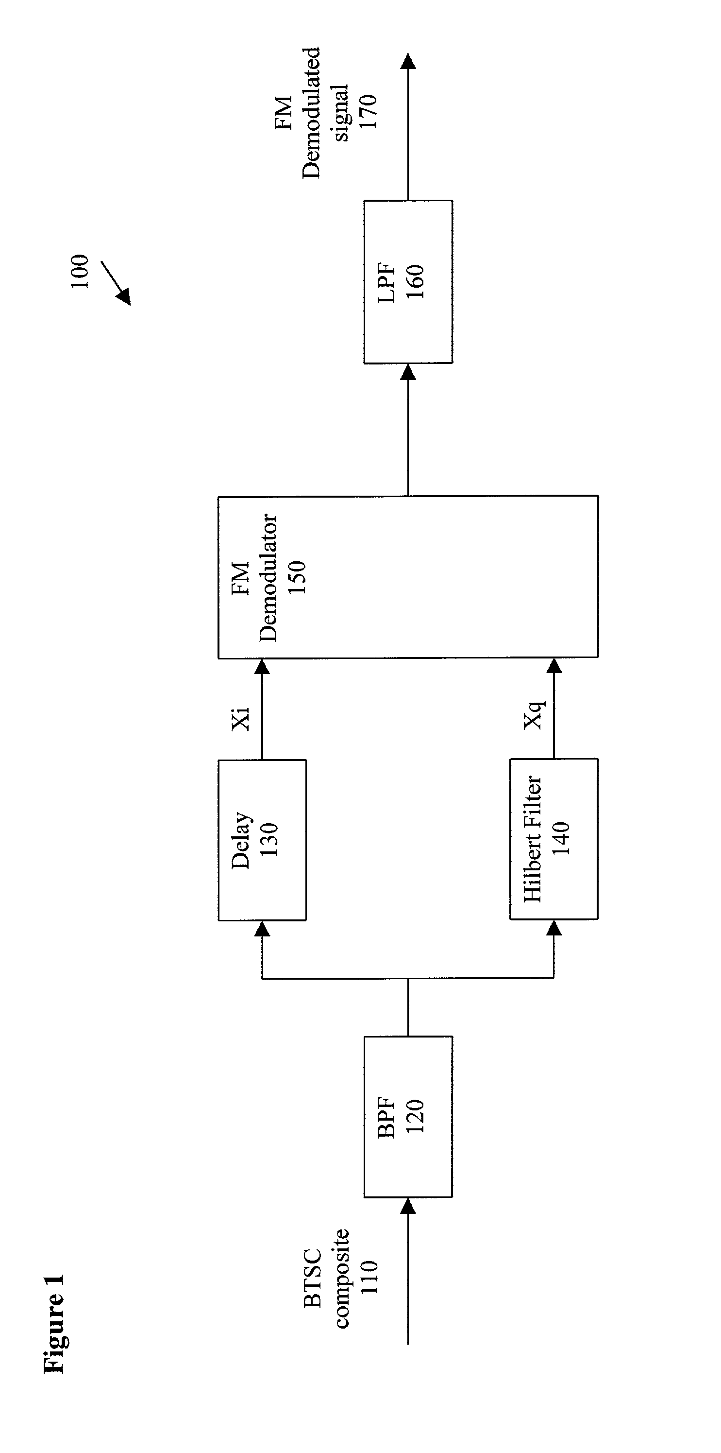
[0018]FIG. 1 illustrates a SAP demodulation system 100, formed in accordance with an embodiment of the present invention. The SAP demodulation system 100 includes a BTSC composite audio signal 110, a bandpass filter (BPF) 120, a delay module 130, a Hilbert filter 140, an FM demodulator 150, and a low pass filter (LPF) 160. The output is an FM demodulated signal 170. The system 100 may be used to demodulate digital FM signals, but, for the purposes of illustration, the system 100 will be described in relation to SAP signal demodulation.

[0019]The BTSC composite audio signal 110 feeds into the BPF 120. After passing through the BPF 120, a filtered signal representing the SAP channel travels to both the delay module 130 and the Hilbert filter 140. The delay module 130 produces a signal Xi that is sent to the FM demodulator 150. The Hilbert filter 140 produces a signal Xq that is sent to the FM demodulator 150. A signal from the FM demodulator 150 enters the LPF 160. The FM demodulated s...


PUM


Abstract

Certain embodiments of the present invention provides a system and method for SAP FM demodulation. The system includes a bandpass filter for isolating the SAP signal, a Hilbert filter to produce a copy of the SAP signal phase shifted by 90 degrees, an FM demodulator for demodulating the SAP signal using the phase shifted SAP signal and a delayed SAP signal, and a lowpass filter to eliminate noise from the FM demodulated SAP signal. The system may also include an automatic gain control for normalizing amplitude of FM demodulator input signals. The digital FM demodulator uses a simplified approximation using non-unity delay for simplified demodulation of frequency modulated signals.

Description

RELATED APPLICATIONS[0001]The application Ser. No. 10 / 083,076 herein references the following applications having Ser. Nos. 10 / 083,052, 10 / 082,950, 10 / 083,203, and 10 / 083,201 filed on the same day as the application Ser. No. 10 / 083,076 herein was filed.BACKGROUND OF THE INVENTION[0002]Certain embodiments of the present invention generally relate to a second audio program (SAP) channel, and in particular, relate to demodulation of a frequency modulation (FM) SAP channel.[0003]Many television programs are enjoyed by audiences speaking a variety of different languages. Therefore, it is desirable to provide audio content in multiple languages along with video content. Additional audio content is typically easier to encode and transmit than video content, so allowing transmission of multiple audio streams with a single video stream may reduce bandwidth and system complexity requirements.[0004]Additionally, information may be provided to supplement an audio or audiovisual program. For exa...

Claims


Application Information

Patent Timeline
Patent Type & Authority Patents(United States)
IPC IPC(8): H04B1/16H04H1/00H04H20/48H04N5/60
CPCH04N21/8106H04N5/607H04N5/602H04H20/48
Inventor WU, DAVID CHAOHUALAMBERT, RUSS
Owner AVAGO TECH WIRELESS IP SINGAPORE PTE
Learn More