Transmitter system for a ferraris motion transmitter

a technology of motion transmitter and transmitter system, which is applied in the direction of instruments, devices using optical means, devices using electric/magnetic means, etc., can solve the problems of measuring errors, other errors, and misalignment between the symmetry axis of the measuring body and the shaft, so as to achieve significant cost savings, enhance sensitivity, and eliminate the effect of magnetic noise fields of the measuring system of the transmitter system

Inactive Publication Date: 2005-04-26
SIEMENS AG
View PDF12 Cites 20 Cited by
  • Summary
  • Abstract
  • Description
  • Claims
  • Application Information

AI Technical Summary

Benefits of technology

[0015]According to another embodiment of the present invention, the transmitter system may include at least two magnetic field sensors, each including, e.g., a coil with at least one winding, wherein the useful fields, effected as a result of the relative movement of the measuring body, in the magnetic field sensors are oppositely directed, and wherein the output signals of the magnetic field sensors are subtracted by the at least two magnetic field sensors. In this way, the sensitivity is enhanced as the useful signals are added up.
[0016]According to another feature of the present invention, there is provided a magnetic shielding for at least partly shielding components of the transmitter system. In this way, magnetic noise fields from the measuring system of the transmitter system can be eliminated. Of course, the magnetic shielding may also be realized by the housing of the transmitter system.
[0017]A transmitter system according to the present invention results in significant cost savings as far as manufacture and assembly thereof are concerned.

Problems solved by technology

Conventional transmitter systems have a mechanical play between measuring body and other components of the transmitter system that may result in measuring errors.
In conjunction with a rotating measuring body, the mechanical play may result in a misalignment between the symmetry axis of the measuring body and the shaft and / or the measuring body is not entirely rotation-symmetric.
Other errors may be caused, for example, through eccentricity, wobbling or inhomogeneities of the measuring body.
This, however, resulted in a more complicated structure of the transmitter system.

Method used


Image

  • Transmitter system for a ferraris motion transmitter
  • Transmitter system for a ferraris motion transmitter
  • Transmitter system for a ferraris motion transmitter

Examples


first embodiment

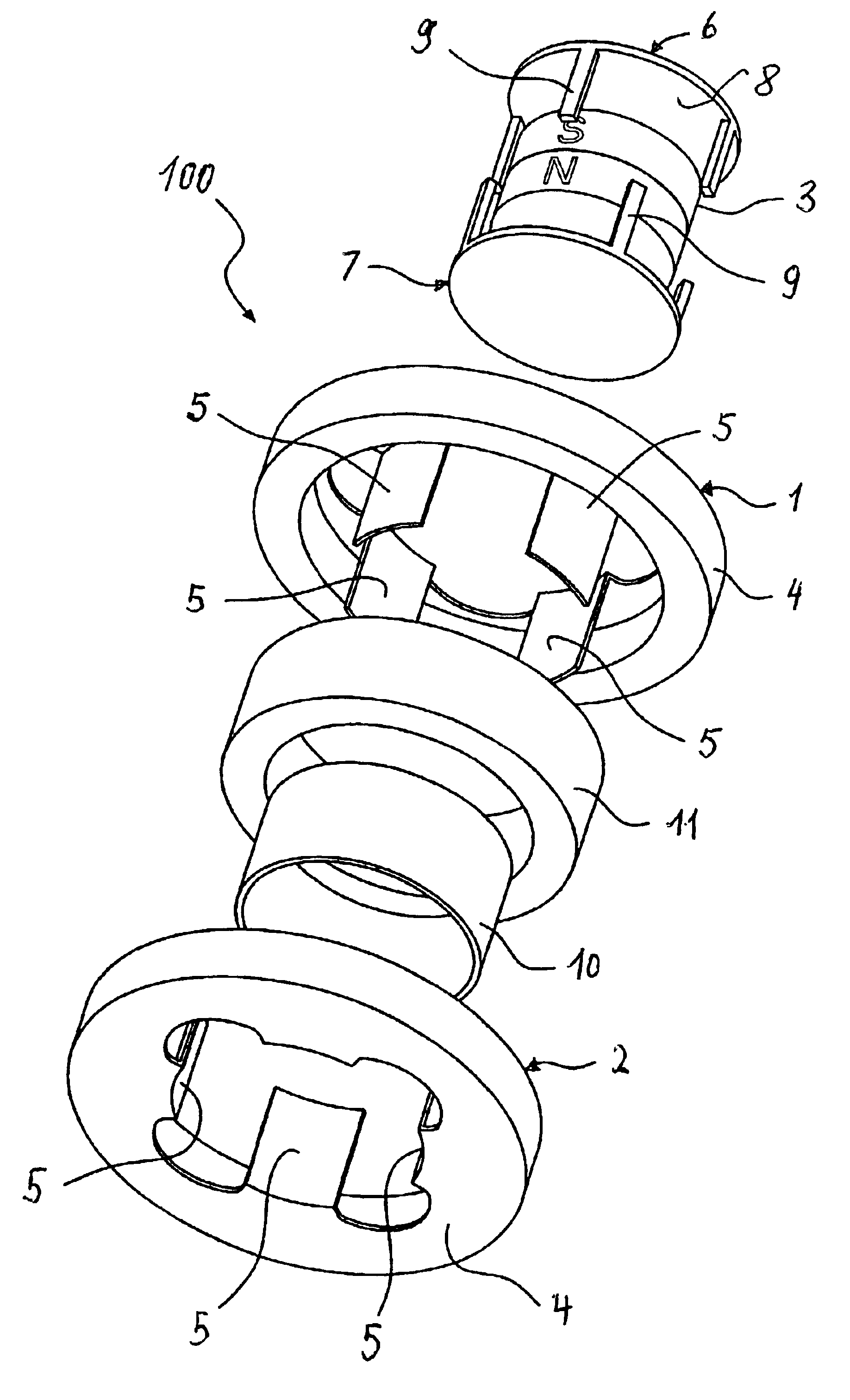
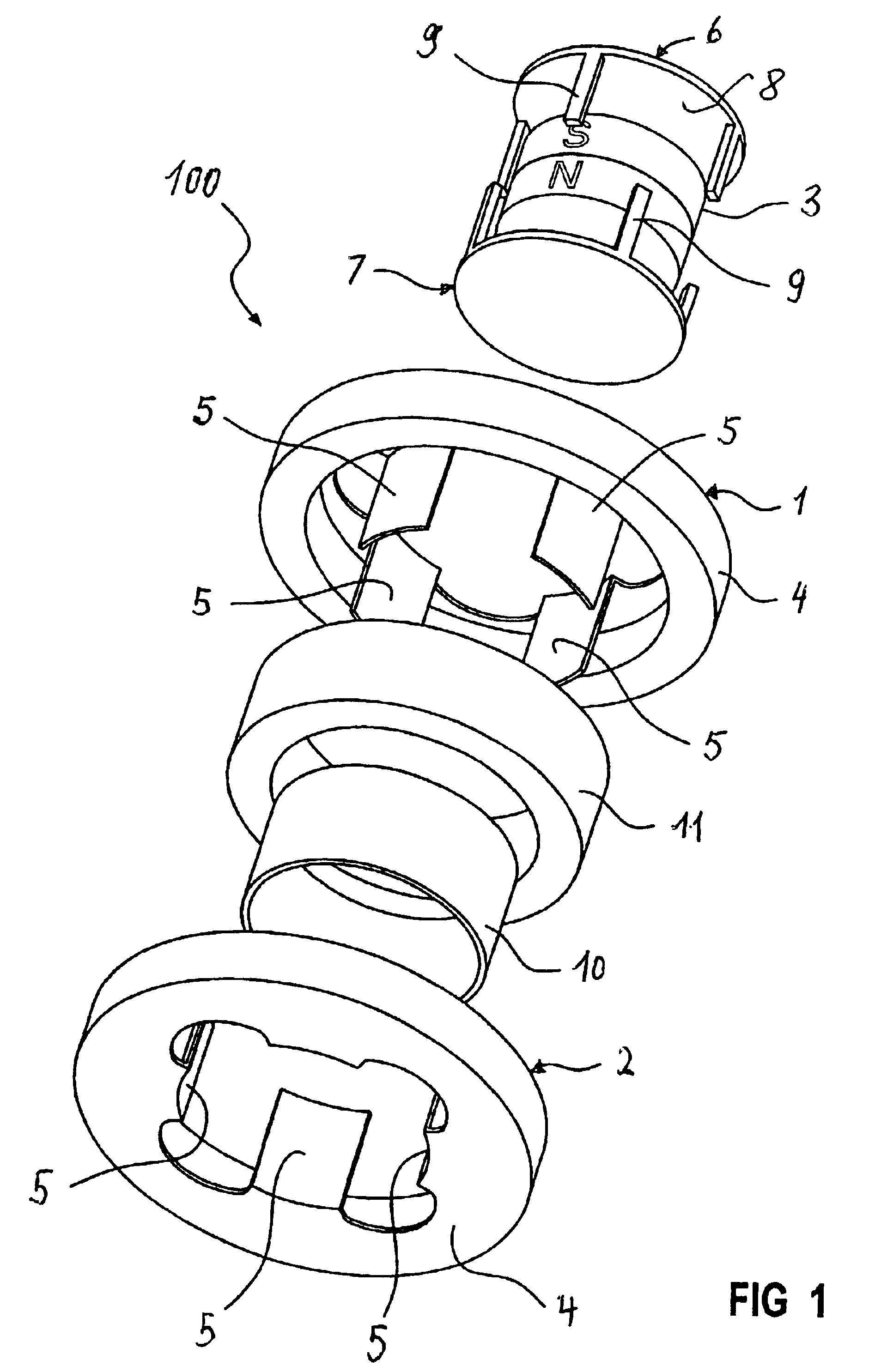
[0026]Turning now to the drawing, and in particular to FIG. 1, there is shown a perspective view, in exploded illustration, of a transmitter system 100 according to the present invention in the form of a Ferraris motion transmitter. The transmitter system 100 includes a magnetic field sensor comprised of a coil 11 and magnetic members in the form of claw-pole rings, generally designated by reference characters 1, 2, and a magnetic field generator 3. The claw-pole rings 1, 2 are of an identical construction, and each includes a carrier 4 which has a plurality of sensor-side claw poles 5. In the assembled state, the claw-pole rings 1, 2 are placed adjacent one another in superimposed disposition, with the claw poles 5 opposing and interlocking one another in parallel relationship to the main axis of the transmitter system 100.

[0027]The magnetic field generator 3 is placed inwardly of the claw-pole rings 1, 2 and has a magnetic north pole N and a magnetic south pole S. Magnetic members...

second embodiment

[0033]FIG. 4 shows a perspective view, in exploded illustration, of a transmitter system in the form of Ferraris motion transmitter according to the present invention, generally designated by reference numeral 200. Parts corresponding with those in FIG. 1 will be identified by corresponding reference numerals followed by an “a”. In this embodiment, the exciter-side claw-pole rings 6a, 7a partly encircle the sensor-side claw-pole rings 1a, 2a with their claw poles 5a. In contrast to the embodiment of FIG. 1, the coil 11a is positioned interiorly in concentric relationship to the claw poles 9a of the exciter-side claw-pole rings 6a, 7a and, at the same time, interiorly in concentric relationship to the claw poles 5a of the sensor-side claw-pole rings 1a, 2a.

[0034]The magnetic field generator 3a of the transmitter system 200 is positioned interiorly in concentric relationship to the sensor coil 11a and the sensor-side claw poles 5a and has a generally cylindrical configuration with ci...


PUM


Abstract

A transmitter system for a Ferraris motion transmitter, includes a magnetic measuring arrangement including at least one magnetic field generator for generating a magnetic field and an electrically conductive measuring body, with the magnetic field generator and the measuring body movable relative to one another in operation. Coupled to the magnetic measuring arrangement is a magnetic field sensor for providing an output signal commensurate with a velocity or acceleration of the measuring body. At least one of the magnetic field generator and the magnetic field sensor includes at least two magnetic members interlocking one another in concentric relationship to the measuring body for guiding the magnetic field as a result of eddy currents forming during operation.

Description

CROSS-REFERENCES TO RELATED APPLICATIONS[0001]This application claims the priority of German Patent Application, Serial No. 101 56 782.0, filed Nov. 19, 2002, pursuant to 35 U.S.C. 119(a)-(d), the disclosure of which is incorporated herein by reference.BACKGROUND OF THE INVENTION[0002]The present invention relates to a transmitter system for a Ferraris motion transmitter.[0003]A typical transmitter system for a Ferraris motion transmitter includes one or more magnetic field generators which form together with an electrically conducting measuring body a magnetic measuring arrangement, whereby magnetic field generator(s) and the measuring body move relative to one another during operation. A magnetic field sensor is linked to the magnetic measuring arrangement to provide a speed-dependent or acceleration-dependent output signal. Such a transmitter system is disclosed, for example, in an article by A. Denne. H. Rausch and W, Freise, entitled “Aufnehmer zur Messung sctinell veränderlich...

Claims


Application Information

Patent Timeline
Patent Type & Authority Patents(United States)
IPC IPC(8): G01P3/42G01D5/12G01P3/49G01D5/20G01P15/00
CPCG01D5/202G01P15/003G01P3/49
Inventor DUENISCH, PAULFINKLER, ROLANDSIESS, RAINERVOLLMER, ROLF
Owner SIEMENS AG
Why Eureka
Try Eureka