Rare earth iron ore magnetic separation equipment

A magnetic separation equipment, iron ore technology, applied in the direction of magnetic separation, solid separation, chemical instruments and methods, etc., can solve the problems of low magnetic field strength, low magnetic separation efficiency, poor effect, etc.

Active Publication Date: 2019-02-19
SHANXI TONGCAI IND & TRADE
View PDF5 Cites 3 Cited by
  • Summary
  • Abstract
  • Description
  • Claims
  • Application Information

AI Technical Summary

Problems solved by technology

[0005] In order to overcome the low magnetic field intensity, low magnetic separation efficiency and poor effect of the existing magnetic separation equipment when performing tailings magnetic separation, a large number of rare earth iron ore magnetic separation is carried out during the magnetic separation process, and the iron ore m

Method used


Image

  • Rare earth iron ore magnetic separation equipment
  • Rare earth iron ore magnetic separation equipment
  • Rare earth iron ore magnetic separation equipment

Examples


Embodiment 1

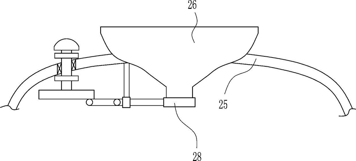
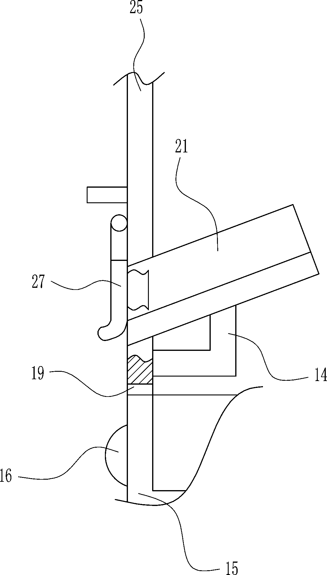
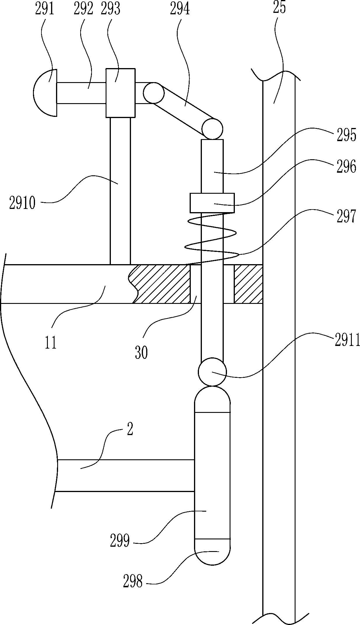
[0029] A rare earth iron ore magnetic separation equipment, such as Figure 1-9 As shown, it includes a small rack 1, a first rotating shaft 2, a motor 3, a runner 4, a sawtooth 5, a moving frame 6, a first pulley 7, a fixed pulley 8, a second pulley 9, a first spring 10, Fixed plate 11, slide rail 12, slider 13, bracket 14, collection tank 15, pull block 16, moving rail 17, roller 18, first electromagnet 20, guide rail 21, slide plate 22, second electromagnet 23, block Plate 24, box body 25 and lower funnel 26, box body 25 left lower wall and right lower wall are all provided with through hole 19, box body 25 inner bottom left and right sides symmetrical formula is provided with moving rail 17, box body 25 inner bottom left and right sides Both sides are symmetrically provided with collection tanks 15, the collection tanks 15 are located above the moving rail 17, the left and right symmetrical rollers 18 are arranged on the bottom of the collection tank 15, the outer surface ...

Embodiment 2

[0031] A rare earth iron ore magnetic separation equipment, such as Figure 1-9 As shown, it includes a small rack 1, a first rotating shaft 2, a motor 3, a runner 4, a sawtooth 5, a moving frame 6, a first pulley 7, a fixed pulley 8, a second pulley 9, a first spring 10, Fixed plate 11, slide rail 12, slider 13, bracket 14, collection tank 15, pull block 16, moving rail 17, roller 18, first electromagnet 20, guide rail 21, slide plate 22, second electromagnet 23, block Plate 24, box body 25 and lower funnel 26, box body 25 left lower wall and right lower wall are all provided with through hole 19, box body 25 inner bottom left and right sides symmetrical formula is provided with moving rail 17, box body 25 inner bottom left and right sides Both sides are symmetrically provided with collection tanks 15, the collection tanks 15 are located above the moving rail 17, the left and right symmetrical rollers 18 are arranged on the bottom of the collection tank 15, the outer surface ...

Embodiment 3

[0034] A rare earth iron ore magnetic separation equipment, such as Figure 1-9 As shown, it includes a small rack 1, a first rotating shaft 2, a motor 3, a runner 4, a sawtooth 5, a moving frame 6, a first pulley 7, a fixed pulley 8, a second pulley 9, a first spring 10, Fixed plate 11, slide rail 12, slider 13, bracket 14, collection tank 15, pull block 16, moving rail 17, roller 18, first electromagnet 20, guide rail 21, slide plate 22, second electromagnet 23, block Plate 24, box body 25 and lower funnel 26, box body 25 left lower wall and right lower wall are all provided with through hole 19, box body 25 inner bottom left and right sides symmetrical formula is provided with moving rail 17, box body 25 inner bottom left and right sides Both sides are symmetrically provided with collection tanks 15, the collection tanks 15 are located above the moving rail 17, the left and right symmetrical rollers 18 are arranged on the bottom of the collection tank 15, the outer surface ...


PUM


Abstract

The invention relates to a magnetic separation device, in particular to rare earth iron ore magnetic separation equipment. The rare earth iron ore magnetic separation equipment achieves oscillating and small-batch magnetic separation of iron ore and has high magnetic separation efficiency. The technical scheme is that the rare earth iron ore magnetic separation equipment comprises a small rack, afirst rotating shaft, a motor, a rotating wheel, sawteeth, a moving frame, a first pulling rope, a fixed pulley, a second pulling rope, a first spring and the like; through holes are arranged in the lower left wall and the lower right walls of a box body; moving rails are symmetrically arranged on the left and right sides of the bottom of the box body; collecting grooves are symmetrically arrangedon the left and right sides of the bottom of the box body; and the collecting grooves are located above the moving rails. The equipment achieves the effect of oscillating and small-batch magnetic separation of the iron ore and high magnetic separation efficiency; through a lower hopper, a small batch of rare earth is released, the rare earth is oscillated and dispersed on a sliding plate, and theiron ore is attracted on the sliding plate and a baffle; in the process, a tapping device works to knock the baffle so that the iron ore can be quickly collected; and the magnetic separation efficiency is high.

Description

technical field [0001] The invention relates to a magnetic separation device, in particular to a rare earth iron ore magnetic separation device. Background technique [0002] Rare earths are known as "industrial vitamins". Now it has become an extremely important strategic resource. Rare earth element oxides refer to oxides of 15 lanthanide elements with atomic numbers from 57 to 71 in the periodic table of elements, and oxides of scandium and yttrium, a total of 17 elements whose chemical properties are similar to lanthanide elements. Rare earth elements have been widely used in petroleum, chemical industry, metallurgy, textile, ceramics, glass plates, permanent magnet materials and other fields. With the advancement of science and technology and continuous breakthroughs in application technology, the value of rare earth oxides will increase . [0003] At present, the ore mined in some areas contains about 30% iron and about 5% rare earth oxides. After the large ore is ...

Claims


Application Information

Patent Timeline
IPC IPC(8): B03C1/02
CPCB03C1/02
Inventor 罗剑
Owner SHANXI TONGCAI IND & TRADE
Why Eureka
Try Eureka