Carton recycling equipment

A technology for recycling equipment and cartons, which is applied in the direction of cleaning hollow objects, presses, grain processing, etc., and can solve problems such as occupation, manual operation, and large area

Inactive Publication Date: 2021-06-18
徐朝应
View PDF10 Cites 0 Cited by
  • Summary
  • Abstract
  • Description
  • Claims
  • Application Information

AI Technical Summary

Problems solved by technology

[0006] Aiming at the deficiencies of the prior art, the present invention provides a carton recycling device, which solves the problem that most of the traditional cartons are directly stored in the warehouse after recycling, occupying a large area, and at the same time, it is easy to be damp and moldy, which seriously reduces the cost of reprocessing the cartons. Product quality, at the same time, some carton compaction devices need to be manually operated, and the use efficiency is low

Method used


Image

  • Carton recycling equipment
  • Carton recycling equipment
  • Carton recycling equipment

Examples


Embodiment 1

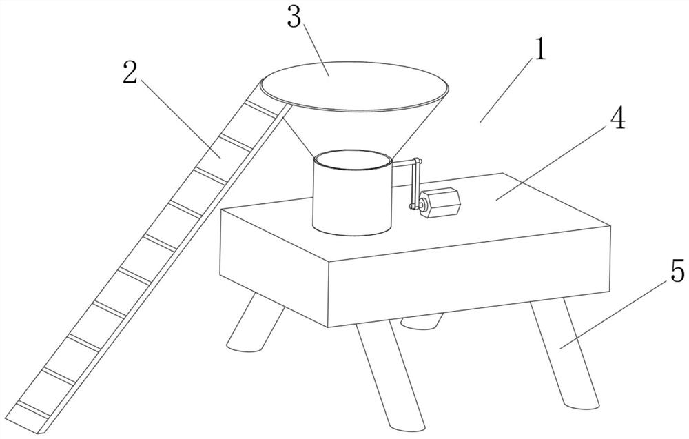
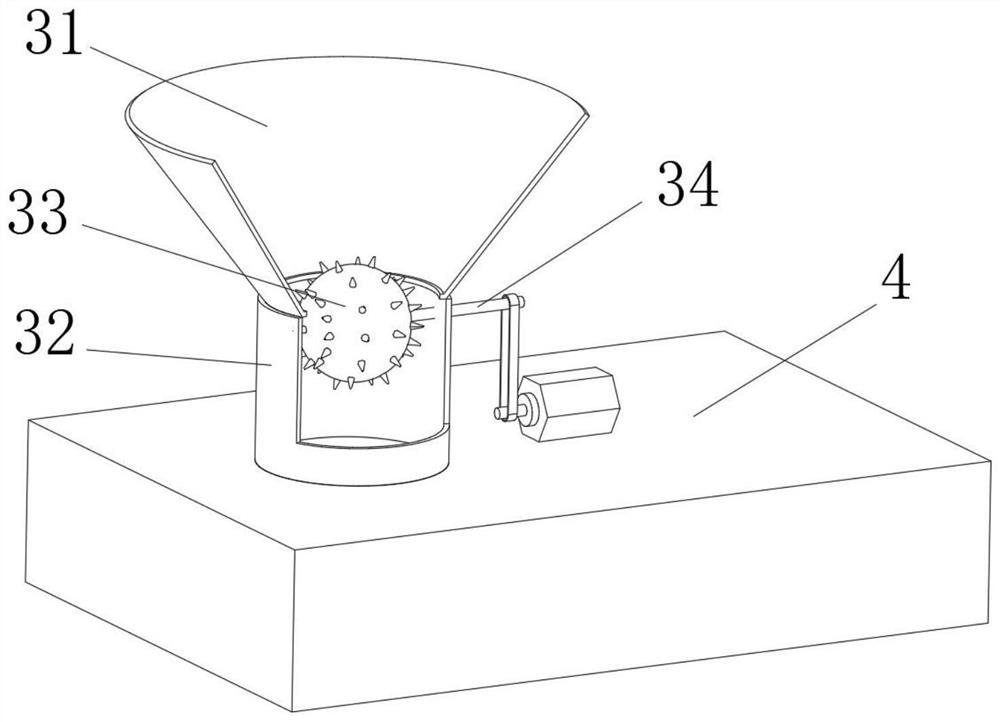
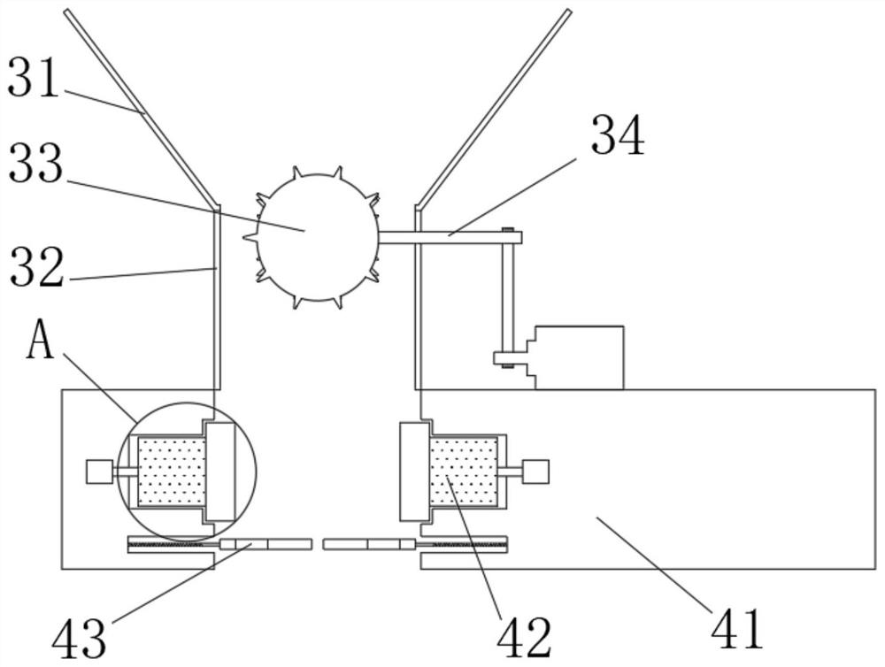
[0042] see Figure 1-4 , the present invention provides a technical solution: a recycling device for cartons, comprising a carton recycling device body 1 composed of a conveyor belt 2, a feeding mechanism 3, an extrusion mechanism 4 and a base 5, the right side of the conveyor belt 2 and the feeding The top of the feeding mechanism 3 is fixedly connected, the bottom of the feeding mechanism 3 communicates with the top of the extruding mechanism 4, the bottom of the extruding mechanism 4 is fixedly connected with the top of the base 5, and the feeding mechanism 3 includes a feeding frame 31. The bottom of frame 31 is fixedly connected with feed pipe 32, and the inside of feed pipe 32 is provided with coiling material mechanism 33, and the inside of coiling material mechanism 33 is fixedly connected with transmission rod 34, and the left end of transmission rod 34 and the inside of feed pipe 32 Rotationally connected, the right end of the transmission rod 34 is rotationally conn...

Embodiment 2

[0048] see Figure 1-5 , on the basis of Embodiment 1, the present invention provides a technical solution: the coiling mechanism 33 includes a solid block 331, the inside of the solid block 331 is fixedly connected to the outside of the transmission rod 34, and the outside of the solid block 331 is fixedly connected There is a magnetic block 332, and the side of the magnetic block 332 away from the middle solid block 331 is fixedly connected with a magnetic bar 333, and the side of the magnetic bar 333 away from the magnetic block 332 is fixedly connected with a blowing mechanism 334 through a receiving rod.

[0049] The blowing mechanism 334 is fixedly connected with a coiled material spheroid 335 on one side away from the magnetic bar 333, and the outer side of the coiled material spheroid 335 is fixedly connected with a coiled material block 336, and the inside of the coiled material spheroid 335 is provided with an air blow hole 337, and the solid block 331 The outer side...

Embodiment 3

[0053] see Figure 1-7 , on the basis of Embodiment 1 and Embodiment 2, the present invention provides a technical solution: the coil block 336 includes an outer connection block 3361, the top of the outer connection block 3361 is fixedly connected with a cutting knife 3362, and the outer side of the outer connection block 3361 The friction knife 3363 is rotatably connected through the reset piece, and the bottom of the outer connection block 3361 is slidably connected with the inside of the rolling material sphere 335 through a telescopic mechanism.

[0054] The air blowing hole 337 includes an elastic membrane 3371, the left side of the elastic membrane 3371 is fixedly connected with the inside of the rolling material sphere 335, the right side of the elastic membrane 3371 is provided with a filter screen 3372, and the inner wall of the elastic membrane 3371 is fixedly connected with an elastic rod 3373.

[0055] When in use, when the coiling mechanism 33 rotates, it drives ...


PUM


Abstract

The invention discloses a carton recycling equipment, and relates to the technical field of carton recycling. The carton recycling equipment comprises a carton recycling equipment body composed of a conveying belt, a feeding mechanism, an extrusion mechanism and a base, the right side of the conveying belt is fixedly connected to the top of the feeding mechanism, the bottom of the feeding mechanism communicates with the top of the extrusion mechanism, the bottom of the extrusion mechanism is fixedly connected to the top of the base, the feeding mechanism comprises a feeding frame, the bottom of the feeding frame is fixedly connected to a feeding pipe, the feeding pipe is internally provided with a material rolling mechanism, and the interior of the material rolling mechanism is fixedly connected to a transmission rod. According to the carton recycling equipment, the problems that after traditional cartons are recycled, most cartons are directly stored in a warehouse, a large area is occupied, meanwhile, the cartons are prone to being affected with damp and mildewing, the product quality of carton reprocessing is seriously reduced, meanwhile, part of carton compacting devices need to be manually operated, and the use efficiency is low are solved.

Description

technical field [0001] The invention relates to the technical field of carton recycling, in particular to a carton recycling device. Background technique [0002] Waste carton recycling is mainly sent to paper mills as raw materials for papermaking. Now the world is in a state of resource shortage, and the production method of paper is to cut down trees to make it, so in order to save resources and avoid waste, after paper products are recycled, they will be remade into pulp, and then made into usable Paper items. [0003] According to Chinese patent CN107953597A, the present invention discloses a compacting device for recycling cartons. The right side of the motor rotates to connect the driving shaft, and the bearing of the driving shaft rotates to connect the body of the device. Connect the driven shaft, the lower end of the boom is sleeved on both sides of the driven shaft, the upper end of the boom is fixed and connected to the body of the device, the two ends of the d...

Claims


Application Information

Patent Timeline
Patent Type & Authority Applications(China)
IPC IPC(8): B02C18/14B02C18/16B02C23/24B30B9/30B08B9/093
CPCB02C18/14B02C18/16B02C23/24B30B9/3089B08B9/093
Inventor 徐朝应
Owner 徐朝应
Why Eureka
Try Eureka