Eureka AIR delivers breakthrough ideas for toughest innovation challenges, trusted by R&D personnel around the world.

Electrolytic filtering/squeezing integrated sludge dewatering machine

A sludge dewatering machine and sludge technology, applied in the direction of dehydration/drying/concentrated sludge treatment, etc., can solve the problems of unsatisfactory, unsatisfactory efficiency, and no sequential increase of filter belt tension, etc., to achieve low investment and high production efficiency , The effect of small equipment occupation

Active Publication Date: 2011-07-06
江苏百新环境工程有限公司
View PDF5 Cites 11 Cited by
  • Summary
  • Abstract
  • Description
  • Claims
  • Application Information

AI Technical Summary

Problems solved by technology

The disadvantage of this technology is that the filter screen and the anode roller always maintain a constant tension, and there is no technical measure to increase the tension of the filter belt in the structure, which cannot meet the demand for gradually increasing the pressing force with the increase in the dryness of the sludge. High dryness of sludge cake cannot be achieved at constant pressure
Secondly, the equipment is separated from the supporting equipment, and the dehydration is completed twice to achieve the expected purpose. The production continuity is not good and the efficiency is not ideal.

Method used

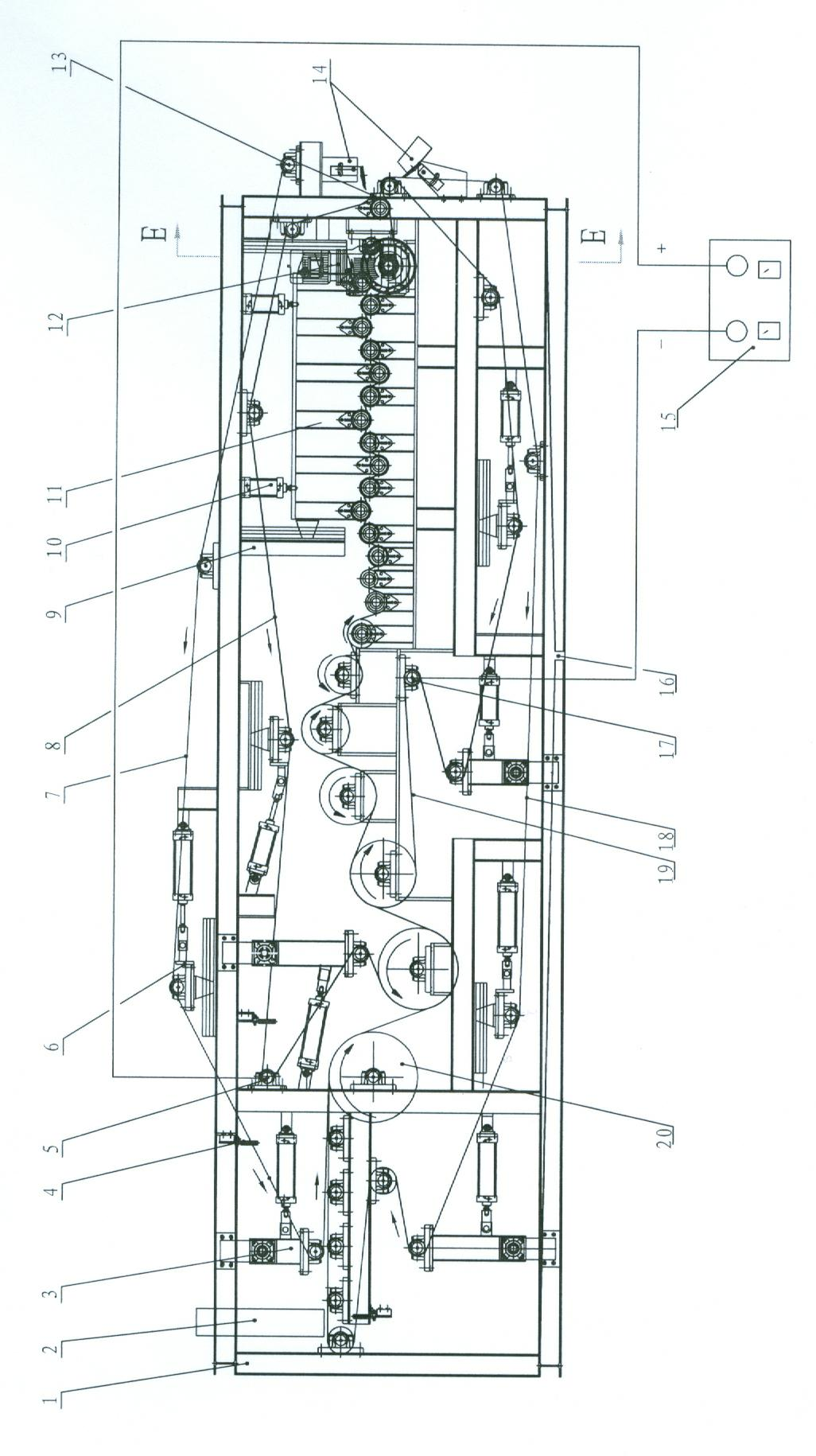
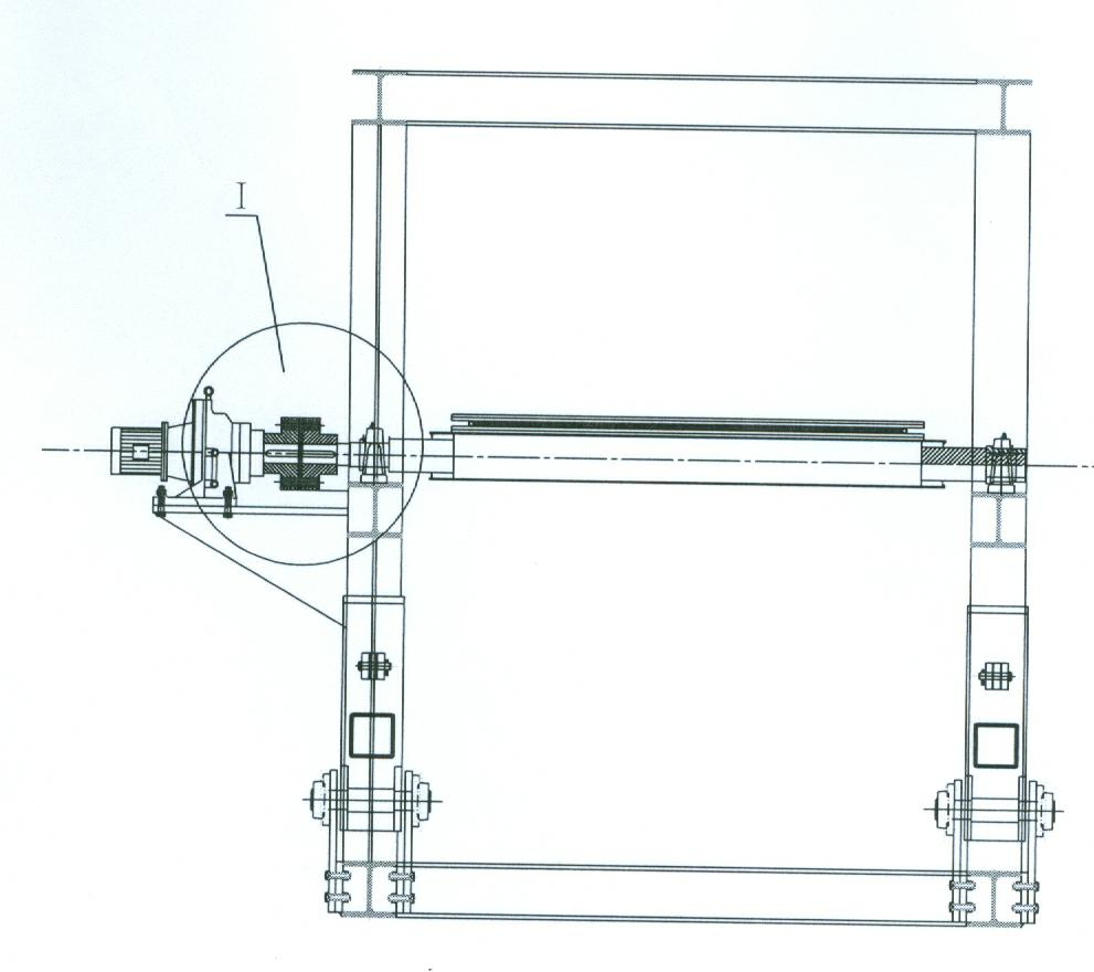
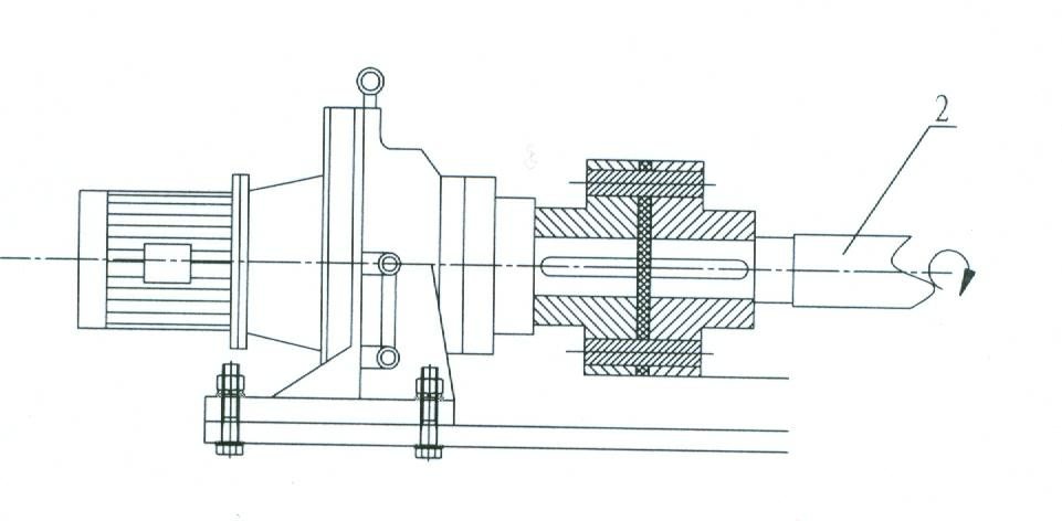

Image

  • Electrolytic filtering/squeezing integrated sludge dewatering machine
  • Electrolytic filtering/squeezing integrated sludge dewatering machine
  • Electrolytic filtering/squeezing integrated sludge dewatering machine

Examples


Embodiment Construction

[0018] The present invention will be further described below according to the accompanying drawings and in conjunction with the embodiments.

[0019] The accompanying drawing is a structural schematic diagram of an embodiment of an electrolytic filter press integrated sludge dewatering machine that processes 20 tons of sludge per day. It includes an initial pressure filter area, an electrolytic filter press, and area and electrolytic pressing area, and an external DC power supply 15. The frame 1 is a rectangular frame in a lying position, with stepped structural brackets installed in order to install horizontal roller shafts 20, and a water accumulation tray 16 is provided at the bottom. The upper and lower parts of the frame 1 are respectively equipped with a tensioning device 3, a deviation correcting device 6 and a guide wheel 13 to jointly support the flexible ring-shaped upper filter belt 7, upper press belt 8, lower filter belt 18, lower press belt 19 and sequentially ar...


PUM


Abstract

The invention discloses an electrolytic filtering / squeezing integrated sludge dewatering machine which comprises a primary squeezing and filtering region, an electrolytic filtering region, an electrolytic squeezing region and an external direct current power source, wherein the primary squeezing and filtering region, the electrolytic filtering region and the electrolytic squeezing region are sequentially arranged with one anther by taking a frame as a carrier. The sludge fallen from a hopper is primarily squeezed and filtered to remove the free water contained in the sludge. A driven upper filter strip and a driven lower filter strip are respectively and externally leaned against an upper squeezing strip and a lower squeezing strip connected the two poles of a direct current power source, so that the sludge clamped between the upper squeezing strip and the lower squeezing strip is electrolyzed, and the interstitial water and the cellular water in the sludge flow to the negative pole when the electric charge flows, i.e. the electrophoresis. The incompletely-dried sludge is carried into the electrolytic squeezing region and is forced under the condition that the sludge is stilled electrolyzed to accelerate the dewatering. By sequentially reducing the diameters of a plurality of the roll shafts and by adopting an installation technology measure that the adjoining roll shafts are installed in a misplaced way up and down, the machine can dewater by sequentially forcing, so that the dryness of a sludge cake is improved. The machine is particularly suitable for treating the biochemical active sludge precipitated by the urban domestic sewage or the industrial sewage.

Description

technical field [0001] The invention relates to an environmental protection equipment, in particular, the invention relates to a sludge dehydrator. Background technique [0002] With the rapid development of urbanization and industrialization, the discharge of domestic sewage and industrial sewage is increasing year by year, resulting in more and more environmental pollution. Sewage has become the key object of contemporary environmental pollution control. Sewage treatment is a large-scale, wide-ranging, highly technical and costly environmental protection project. There are many kinds of sewage treatment technologies in the market, no matter what kind of sewage treatment technology is adopted, sludge will be left in the end. The sedimented pollution is in the form of paste, which is large in size and difficult to dispose of. The sewage treatment plant must fully dehydrate the accumulated sludge in order to achieve the purpose of sludge reduction, resource utilization, and ...

Claims


Application Information

Patent Timeline
IPC IPC(8): C02F11/12
Inventor 张宪如张慧王磊
Owner 江苏百新环境工程有限公司
Why Eureka
Eureka Blog
Learn More