Convenient and efficient device for scrubbing away dirt during bath
An efficient and convenient technology, applied in home appliances, sanitary equipment, applications, etc., can solve problems such as difficult scrubbing and insufficient bathing effect, and achieve the effect of avoiding manual scrubbing, sufficient scrubbing, and avoiding manual smearing
- Summary
- Abstract
- Description
- Claims
- Application Information
AI Technical Summary
Problems solved by technology
Method used
Image

Examples
Embodiment 1
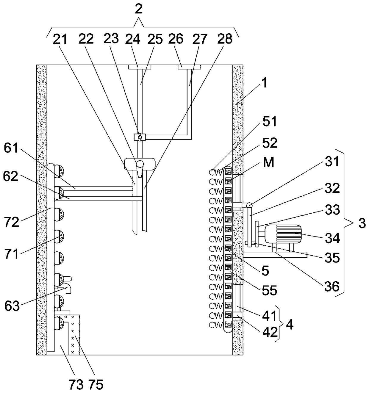
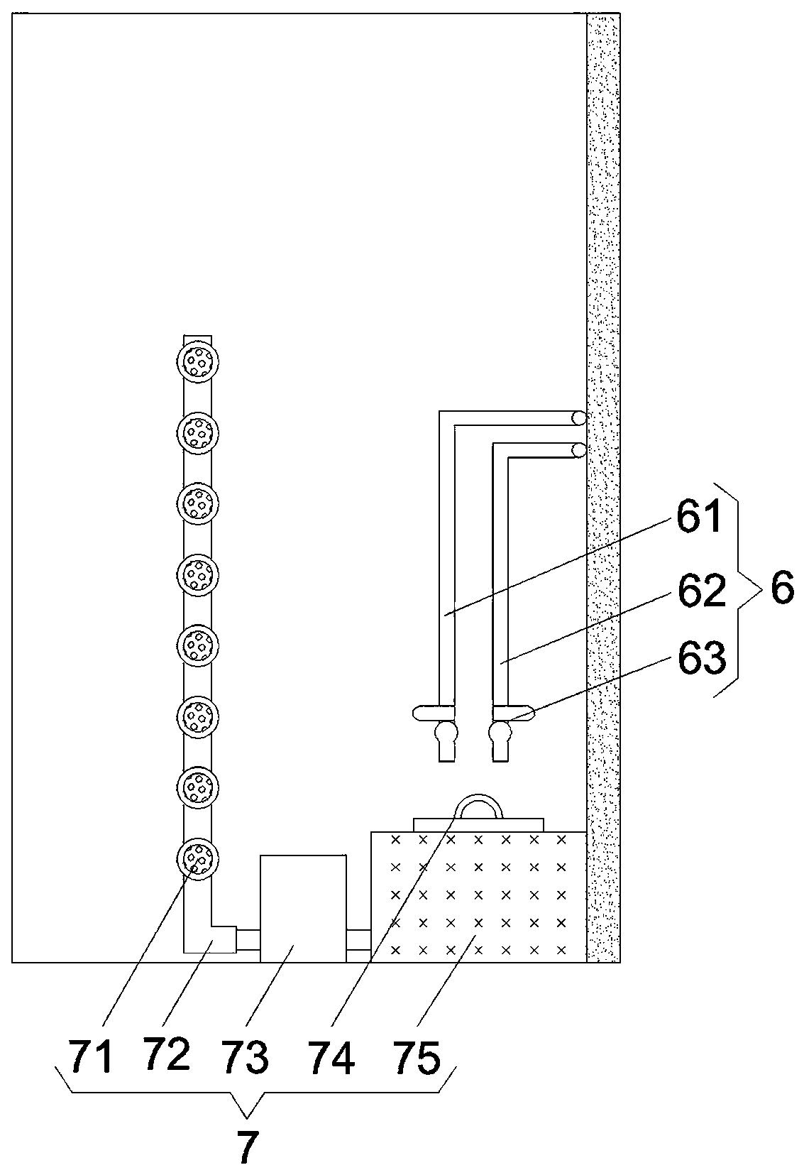
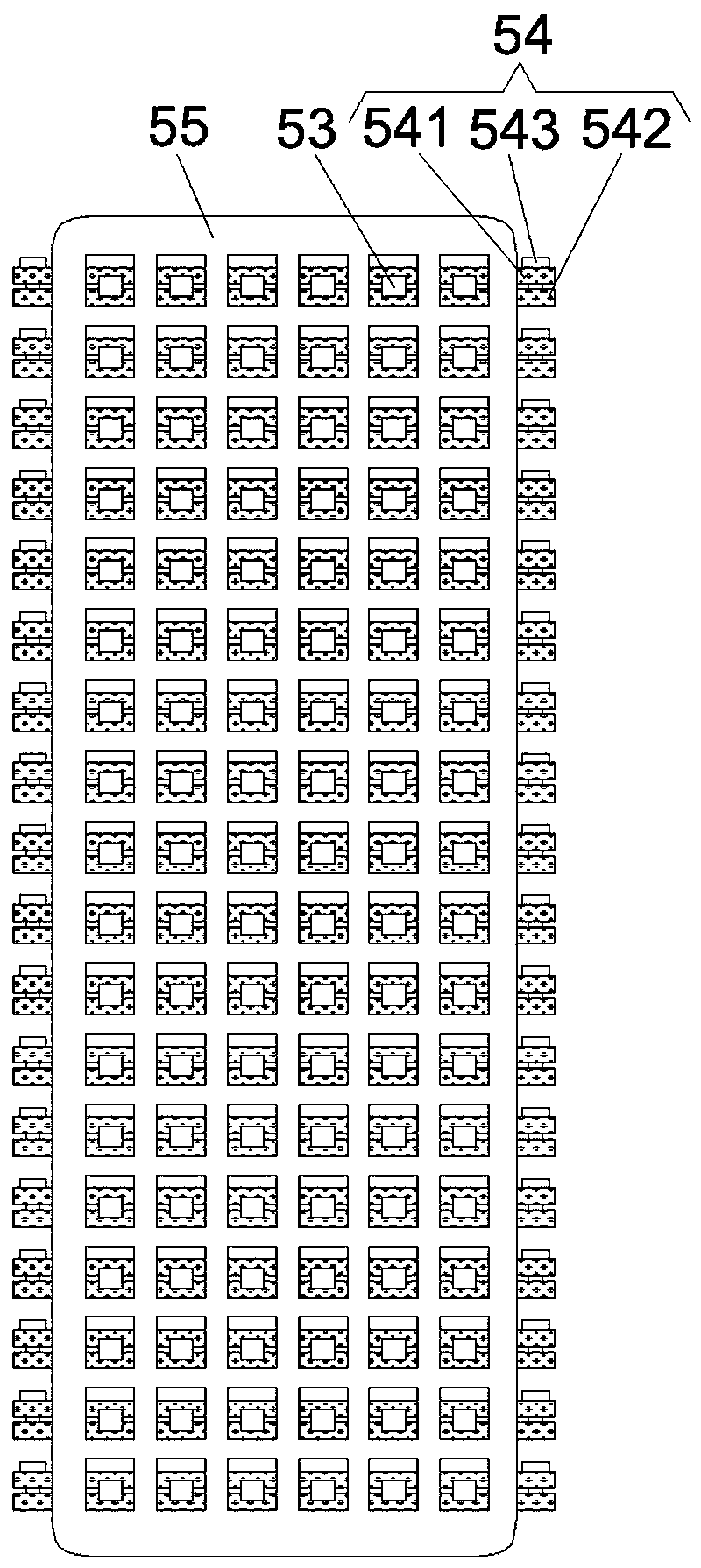
[0028] see Figure 1-3 , the present invention provides the following technical solutions: a convenient and efficient bathing ash rubbing device, comprising a shelf 1 and a flushing mechanism 2, the flushing mechanism 2 is arranged on the rear side of the shelf 1, and the flushing mechanism 2 is arranged to facilitate the completion of bathing. The flushing action, on the right side of the frame plate 1 is provided with a rubbing mechanism 5, on the right side of the frame plate 1 is provided with a driving mechanism 3, the rubbing mechanism 5 and the driving mechanism 3 are connected by at least two connection positioning mechanisms 4 , each connection positioning mechanism 4 is all arranged on the inside of the right side plate of the shelf plate 1, and the mutual cooperation of the rubbing mechanism 5, the connection positioning mechanism 4 and the driving mechanism 3 is convenient for completing the rubbing action when taking a bath. The left side of the interior is respec...
PUM
 Abstract
Description
Claims
Application Information
 - Generate Ideas
- Intellectual Property
- Life Sciences
- Materials
- Tech Scout
- Unparalleled Data Quality
- Higher Quality Content
- 60% Fewer Hallucinations
Browse by: Latest US Patents, China's latest patents, Technical Efficacy Thesaurus, Application Domain, Technology Topic, Popular Technical Reports.
© 2025 PatSnap. All rights reserved.Legal|Privacy policy|Modern Slavery Act Transparency Statement|Sitemap|About US| Contact US: help@patsnap.com