Method and device for predicting ground leakage fault of train power supply system

A power supply system and grounding leakage technology, which is used in measuring devices, testing electrical devices in transportation, measuring electricity, etc., can solve the problems of complex structure of train power supply system, complex application environment, and inability to evaluate fault status, and achieve high-precision grounding. The effect of leakage fault prediction, maintenance cost reduction, reliability improvement and continuous operation capability

Active Publication Date: 2019-03-01
ZHUZHOU CSR TIMES ELECTRIC CO LTD
View PDF5 Cites 5 Cited by
  • Summary
  • Abstract
  • Description
  • Claims
  • Application Information

AI Technical Summary

Problems solved by technology

[0004] At present, although there are prediction methods for equipment failure, they are usually based on the failure prediction of a certain key component in the equipment. However, the structure of the train power supply system is complex, the application environment is complex, and there are many failure modes for earth leakage faults, such as figure 2 As shown, there are mainly 8 types of earth leakage faults: rectification side positive terminal (1), rectification side negative terminal (2), reactance front stage (3), DC600V positive output terminal (4), DC600V negative output terminal (5) , the ground faults of phase A (6) on the inverter side, phase B (7) on the inverter side, and phase C (8) on the inverter side. Each type of ground leakage fault has a different location in the power supply system. The fault state prediction of the power supply system cannot evaluate the overall fault state of the power supply system, so the existing fault prediction method based on key components cannot be directly adapted to the train power supply system

Method used


Image

  • Method and device for predicting ground leakage fault of train power supply system
  • Method and device for predicting ground leakage fault of train power supply system
  • Method and device for predicting ground leakage fault of train power supply system

Examples


Embodiment Construction

[0054] The present invention will be further described below in conjunction with the accompanying drawings and specific preferred embodiments, but the protection scope of the present invention is not limited thereby.

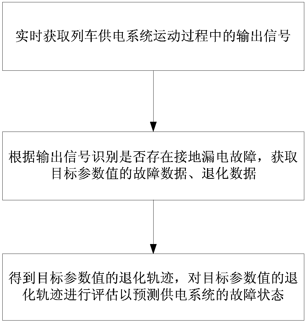
[0055] Such as image 3 As shown, the steps of the method for predicting the ground leakage fault of the train power supply system in this embodiment include:

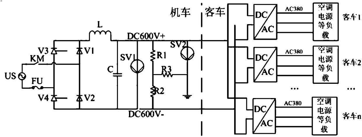
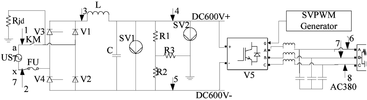
[0056] S1. Signal acquisition: real-time acquisition of the output signal during the movement of the train power supply system;

[0057] S2. Fault real-time monitoring: Identify whether there is a ground leakage fault based on the output signal obtained in real time. If a fault is identified, obtain the target parameter value of the power supply system in the current fault state, and obtain the fault data of the target parameter value, otherwise obtain the target parameter degenerate data of value;

[0058] S3. Fault state prediction: Obtain the fault data and degradation data of the target parameter v...


PUM


Abstract

The invention discloses a method and device for predicting a ground leakage fault of a train power supply system. The method steps include: S1, acquiring an output signal during the movement of the train power supply system in real time; S2, determining whether there is a ground leakage fault according to the output signal obtained in real time, obtaining the target parameter value of the power supply system in a current fault state and the fault data of the target parameter value if so, otherwise obtaining the degradation data of the target parameter value; and S3, obtaining the fault data and the degradation data of the target parameter value in a specified time period, obtaining the degradation trajectory of the target parameter value, and evaluating the degradation trajectory of the target parameter value to predict the fault state of the power supply system. The device includes a signal acquisition module, a fault real-time monitoring module and a fault status prediction module. The method is easy to achieve, can monitor the ground leakage fault of the power supply system and predict the fault state, and achieves high prediction precision.

Description

technical field [0001] The invention relates to the technical field of train power supply, in particular to a method and device for predicting ground leakage faults of a train power supply system. Background technique [0002] The train power supply system runs through the entire locomotive and passenger car, such as figure 1 As shown, the power supply system in the locomotive adopts AC-DC-AC structure, including rectifier unit, DC power supply unit, inverter output unit, etc. The entire power supply system includes various equipment in the power supply system of locomotives and buses. In the normal state, there is no current flowing in the protective ground. When a ground fault occurs, a circuit is formed, resulting in leakage current, that is, a leakage fault occurs. Since the power supply system is in the working state for a long time, the insulation performance of each equipment in the power supply system will gradually degrade. , if the insulation performance is reduce...

Claims


Application Information

Patent Timeline
Patent Type & Authority Applications(China)
IPC IPC(8): G01R31/02
CPCG01R31/008G01R31/50
Inventor 李子先郭建刘灿郝洪伟林波任三刚蔡杰姚晓东唐娟谢佳彬
Owner ZHUZHOU CSR TIMES ELECTRIC CO LTD
Why Eureka
Try Eureka