An integrated electro-hydraulic braking system that actively switches driving styles
What is Al technical title?
Al technical title is built by PatSnap Al team. It summarizes the technical point description of the patent document.
A driving style, hydraulic braking technology, applied in the direction of brakes, brake transmissions, vehicle components, etc., can solve the problems of continuously adjustable power assist ratio, insufficient integration, complex structure, etc., to achieve personalized customization Effect
Active Publication Date: 2019-05-28
JILIN UNIV
View PDF6 Cites 0 Cited by
Summary
Abstract
Description
Claims
Application Information
AI Technical Summary
This helps you quickly interpret patents by identifying the three key elements:
Problems solved by technology
Method used
Benefits of technology
Problems solved by technology
[0005] The present invention provides an integrated electronic hydraulic braking system that actively switches driving styles in order to solve the problems that the current electronic hydraulic braking system is not highly integrated, has a complex structure, and cannot realize continuous adjustment of the assist ratio according to the driving style.
Method used
Image
Click on the blue label to locate the original text in one second.
Reading with bidirectional positioning of images and text.
Examples
Embodiment Construction
[0068] see Figure 1 to Figure 9 Shown:
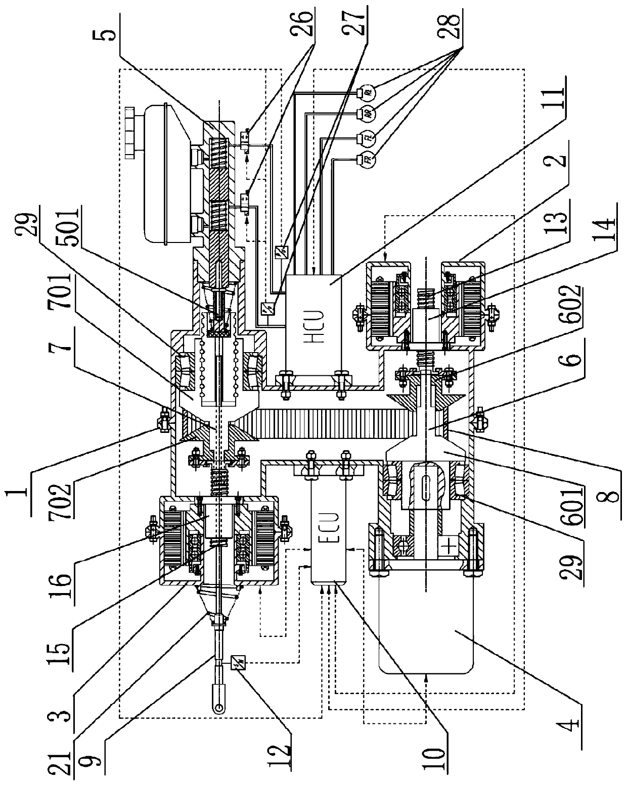
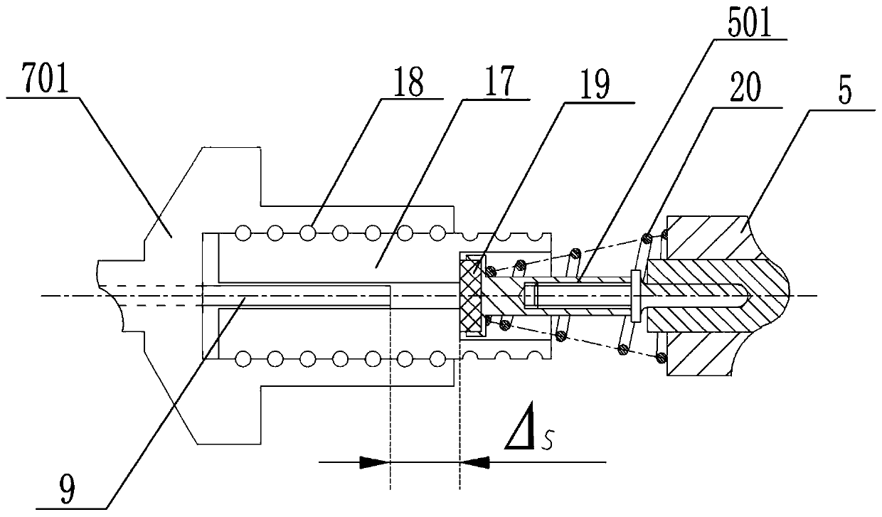
[0069] The present invention includes a housing 1, a first motor 2, a second motor 3, a booster motor 4, a brake master cylinder 5, a driving wheel 6, a driven wheel 7, a transmission belt 8, a brake pedal push rod 9, a first transmission pair, The second transmission pair, the third transmission pair, the electronic control unit ECU10, the hydraulic control unit HCU11 and the pedal travel sensor 12, the first motor 2, the second motor 3, the booster motor 4, the brake master cylinder 5, the electric control The unit ECU10 and the hydraulic control unit HCU11 are respectively arranged on the housing 1;
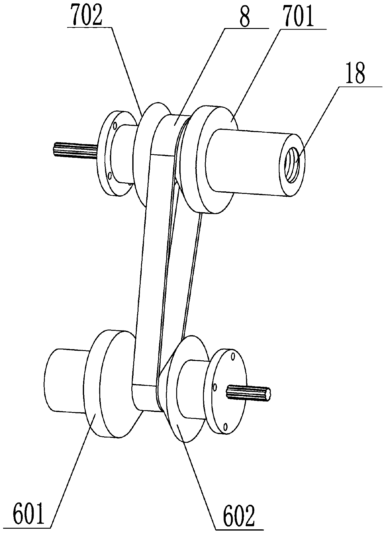
[0070] The driving wheel 6 and the driven wheel 7 are arranged inside the housing 1 in parallel, and the transmission belt 8 is sleeved on the driving wheel 6 and the driven wheel 7, and the driving wheel 6 and the driven wheel 7 are connected in transmission; the driving wheel 6 includes a fixed end 601 of the driving wheel and The ...
PUM
Abstract
The invention relates to an integrated electronic hydraulic braking system capable of actively switching driving styles, and aims at solving the problems of poorer integrated level, complicated structure and failure of achieving the continuous adjustment of boost ratio according to driving styles of a current electronic hydraulic braking system. The system comprises a housing, a first motor, a second motor, a boost motor, a braking main cylinder, a driving wheel, a driven wheel, a transmission belt, a braking pedal push rod, first transmission pairs, second transmission pairs, third transmission pairs, an electric control unit (ECU), a hydraulic control unit (HCU) and a pedal travel sensor, wherein the first motor, the second motor, the boost motor, the braking main cylinder, the electriccontrol unit (ECU) and the hydraulic control unit (HCU) are arranged on the housing. By means of the integrated electronic hydraulic braking system, the continuous adjustment of braking boost ratio isachieved, the boost ratios with any magnitudes can be selected according to the wills of drivers, the free switching of the driving styles is completed, and the system is conformed to the developingtendency of driving style customization in a current intelligent driving technology.
Description
technical field [0001] The invention relates to a braking system, in particular to an integrated electronic hydraulic braking system for actively switching driving styles. Background technique [0002] In recent years, the continuous progress of automobile intelligent technology and electrification technology has put forward higher requirements for the automobile braking system. To charge the battery to increase the cruising range, it can be used as an important underlying actuator of the intelligent driving assistance system, which can realize the arbitrary switching of different driving styles, that is, the brake booster ratio can be adjusted, which can make different drivers change according to their own preferences. driving style. In order to conform to the development trend of automobile intelligence and electrification, the application of traditional vacuum booster braking system is gradually decreasing, and the research on electrohydraulic braking system has become a...
Claims
Application Information
Patent Timeline
Application Date:The date an application was filed.
Publication Date:The date a patent or application was officially published.
First Publication Date:The earliest publication date of a patent with the same application number.
Issue Date:Publication date of the patent grant document.
PCT Entry Date:The Entry date of PCT National Phase.
Estimated Expiry Date:The statutory expiry date of a patent right according to the Patent Law, and it is the longest term of protection that the patent right can achieve without the termination of the patent right due to other reasons(Term extension factor has been taken into account ).
Invalid Date:Actual expiry date is based on effective date or publication date of legal transaction data of invalid patent.