Optical imaging system

An optical imaging system and optical axis technology, applied in the field of optics, can solve the problems of imaging quality and miniaturization design.

Pending Publication Date: 2019-03-08
ZHEJIANG SUNNY OPTICAL CO LTD
View PDF0 Cites 11 Cited by
  • Summary
  • Abstract
  • Description
  • Claims
  • Application Information

AI Technical Summary

Problems solved by technology

[0006] The main purpose of the present invention is to provide an optical imaging system to solve the problem that the imaging quality and miniaturization design of the optical imaging system in the prior art cannot be combined

Method used


Image

  • Optical imaging system
  • Optical imaging system
  • Optical imaging system

Examples


Embodiment 1

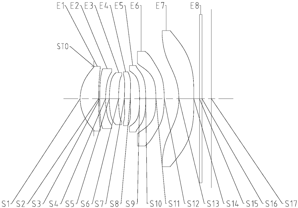
[0060] like figure 1 As shown, along the direction from the object side to the image side along the optical axis, the optical imaging system sequentially includes a stop STO, a first lens E1, a second lens E2, a third lens E3, a fourth lens E4, and a fifth lens E5 , the sixth lens E6, the seventh lens E7, the filter E8 and the imaging surface S17.

[0061] The first lens has positive refractive power, and the object side of the first lens is convex and aspheric, and the image side is concave and aspherical; the second lens has negative refractive power, and the object side of the second lens is Convex and aspheric, the image side is concave and aspheric; the third lens has positive power, and the object side of the third lens is convex and aspheric, and the image side is concave and aspherical; The fourth lens has positive refractive power, and the object side of the fourth lens is convex and aspherical, and the image side is concave and aspheric; the fifth lens has negative ...

Embodiment 2

[0078] like image 3 As shown, along the direction from the object side to the image side along the optical axis, the optical imaging system sequentially includes a first lens E1, a second lens E2, a third lens E3, a fourth lens E4, a fifth lens E5, and a sixth lens E6, seventh lens E7, filter E8 and imaging surface S17.

[0079] The first lens has positive refractive power, and the object side of the first lens is convex and aspheric, and the image side is concave and aspherical; the second lens has negative refractive power, and the object side of the second lens is Convex and aspheric, the image side is concave and aspheric; the third lens has positive power, and the object side of the third lens is convex and aspheric, and the image side is concave and aspherical; The fourth lens has positive refractive power, and the object side of the fourth lens is convex and aspherical, and the image side is concave and aspheric; the fifth lens has positive refractive power, and the o...

Embodiment 3

[0094] like Figure 5 As shown, along the direction from the object side to the image side along the optical axis, the optical imaging system sequentially includes a first lens E1, a second lens E2, a diaphragm STO, a third lens E3, a fourth lens E4, and a fifth lens E5 , the sixth lens E6, the seventh lens E7, the filter E8 and the imaging surface S17.

[0095] The first lens has positive refractive power, and the object side of the first lens is convex and aspheric, and the image side is concave and aspherical; the second lens has negative refractive power, and the object side of the second lens is Convex and aspheric, the image side is concave and aspheric; the third lens has positive power, and the object side of the third lens is convex and aspheric, and the image side is concave and aspherical; The fourth lens has positive refractive power, and the object side of the fourth lens is convex and aspherical, and the image side is concave and aspheric; the fifth lens has pos...


PUM


Abstract

The invention provides an optical imaging system. The system sequentially comprises a first lens, a second lens, a third lens, a fourth lens, a fifth lens, a sixth lens and a seventh lens from the object side to the image side along the optical axis; the first lens has positive focal power; the second lens has negative focal power; the object side face of the sixth lens is a concave surface; the seventh lens has negative focal power; f is the effective focal length of the optical imaging system, the effective focal length of the fourth lens is f4, the effective focal length of the fifth lens is f5, and |f / f4|+|f / f5| is smaller than or equal to 0.3. The system solves the problem that the imaging quality and miniaturization design of an optical imaging system in the prior art cannot be achieved at the same time.

Description

technical field [0001] This application relates to the field of optics, in particular, to an ultra-thin, long-focus seven-chip optical imaging system. Background technique [0002] With the continuous development of science and technology, people have higher and higher requirements for optical imaging systems. [0003] Specifically, in order to meet people's needs, the imaging quality of the optical imaging system needs to be further improved. The telephoto camera module can clearly capture distant scenes, produce a sense of spatial compression, and can highlight the subject information and blur the background. , and thus more and more people of all ages, occupy a place in the optical imaging system market. [0004] Not only that, with the development of portable electronic products such as smartphones, the market has also put forward higher requirements for the miniaturization and weight reduction of optical imaging systems. In order to meet the miniaturization design req...

Claims


Application Information

Patent Timeline
Patent Type & Authority Applications(China)
IPC IPC(8): G02B13/00G02B13/18
CPCG02B13/0045G02B13/18
Inventor 黄林张战飞
Owner ZHEJIANG SUNNY OPTICAL CO LTD
Why Eureka
Try Eureka