Orthodontic assist device
An auxiliary device and orthodontic technology, applied in the field of oral medicine, can solve problems such as loss of anchorage, slow movement, immobility, etc., achieve good adaptability, meet the needs of tooth shape and oral cavity, and fix the effect of simple operation
- Summary
- Abstract
- Description
- Claims
- Application Information
AI Technical Summary
Problems solved by technology
Method used
Image
Examples
Embodiment approach 1
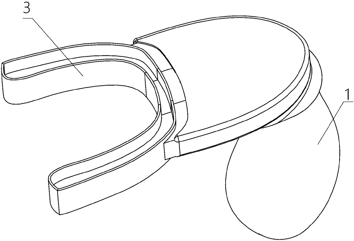
[0061] The first embodiment of the present invention provides an orthodontic aid, see figure 1 and figure 2 As shown, it includes: a housing 1 and a vibrating device 2 arranged in the housing 1, and the vibrating device 2 is used to generate vibration;
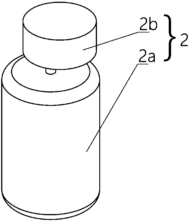
[0062] see figure 2 As shown, the vibrating device 2 is realized by any device capable of reciprocating motion in the prior art. Typically, it may include a motor 2a and an eccentric wheel 2b connected in series to the motor 2a; the motor 2a drives the eccentric wheel 2b to rotate and generate periodic vibrations. Wherein, the motor 2a can be various motors in the prior art, in particular, it can be a linear motor.
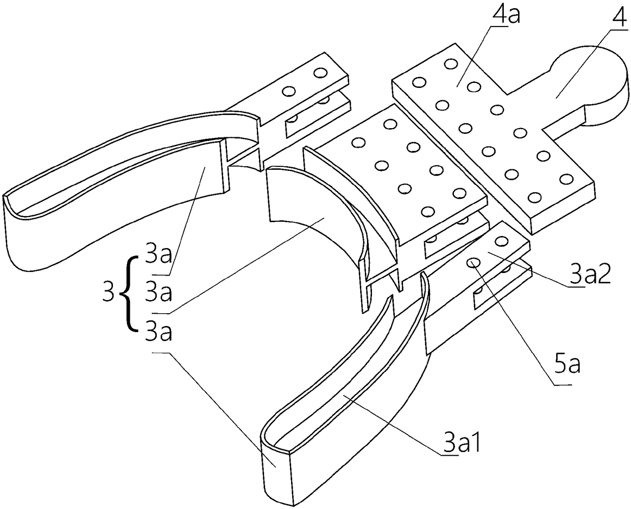
[0063] see image 3 As shown, the orthodontic auxiliary device also includes a connecting piece 4 that is partly located inside the housing 1 and the rest is located outside the housing 1, and one end of the connecting piece 4 located outside the housing 1 is provided with a connecting portion 4a;
[0064] ...
Embodiment approach 2
[0089] The second embodiment of the present invention provides an orthodontic aid. The second embodiment is different from the first embodiment. The main difference is that in the first embodiment of the present invention, the extension part 3a2 and the connection The parts 4a are fixed to each other by bolts 5b; and in the second embodiment of the present invention, the extension part 3a2 and the connecting part 4a are engaged and fixed to each other.
[0090] Specifically, see Figure 6 As shown, in this embodiment, a protrusion 5c is formed on the extension part 3a2, and a track groove 5d is formed on the connecting part 4a;
[0091] see Figure 7 As shown, the protrusion 5c fits into the track groove 5d and fixes the extension part 3a2 and the connecting part 4a to each other.
[0092]In this embodiment, the tray 3 a can be well fixed on the connecting member 4 by virtue of the protrusion 5 c engaging with the track groove 5 d. As a further preference of this embodiment...
Embodiment approach 3
[0096] The third embodiment of the present invention provides an orthodontic aid, the third embodiment is a further improvement of the second embodiment, the main improvement is that, in the third embodiment of the present invention, see Figure 8 As shown, stop switches 5f for locking the protrusions 5c of the extensions 3a2 of each tray 3a in the track grooves 5d are provided on the connecting portion 4a near both ends of the track grooves 5d.
[0097] Such as Figure 8 As shown, when the limit switch 5f is turned on, the protrusion 5c can be embedded in the track groove 5d very conveniently, and after each tray 3a is installed, see Figure 9 As shown, the stop switch 5f is locked back, and the fixing of the tray 3a is completed.
[0098] Stop switches 5f are provided at both ends of the track groove 5d to prevent the protrusion 5c from sliding in the track groove 5d during the vibration process, and prevent the protrusion 5c from falling off from the track groove 5d, so th...
PUM
 Abstract
Description
Claims
Application Information
 - R&D
- Intellectual Property
- Life Sciences
- Materials
- Tech Scout
- Unparalleled Data Quality
- Higher Quality Content
- 60% Fewer Hallucinations
Browse by: Latest US Patents, China's latest patents, Technical Efficacy Thesaurus, Application Domain, Technology Topic, Popular Technical Reports.
© 2025 PatSnap. All rights reserved.Legal|Privacy policy|Modern Slavery Act Transparency Statement|Sitemap|About US| Contact US: help@patsnap.com


