Light-emitting keyboard

A technology of luminous keyboards and buttons, which is applied in legends, electrical components, electric switches, etc., can solve the problems of occupying space and unfavorable thinning of luminous keyboards

Inactive Publication Date: 2019-03-19
PRIMAX ELECTRONICS LTD
View PDF4 Cites 1 Cited by
  • Summary
  • Abstract
  • Description
  • Claims
  • Application Information

AI Technical Summary

Problems solved by technology

However, the structure that the sides of the reflective sheet 233 must be attached to the light-shielding sheet 234 ...

Method used


Image

  • Light-emitting keyboard
  • Light-emitting keyboard
  • Light-emitting keyboard

Examples


Embodiment Construction

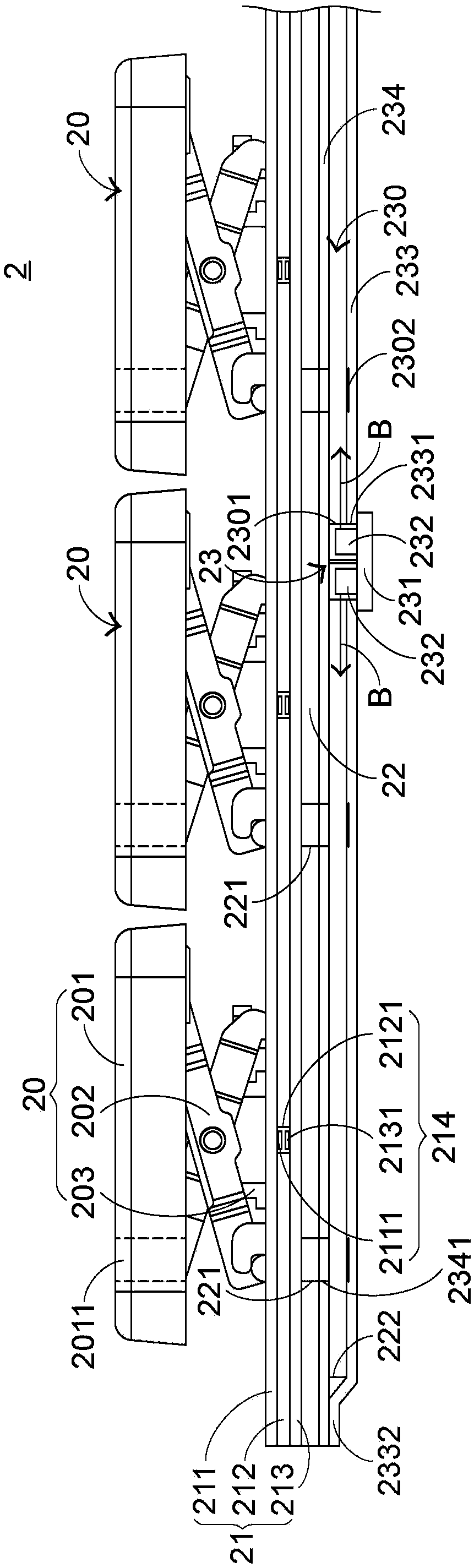
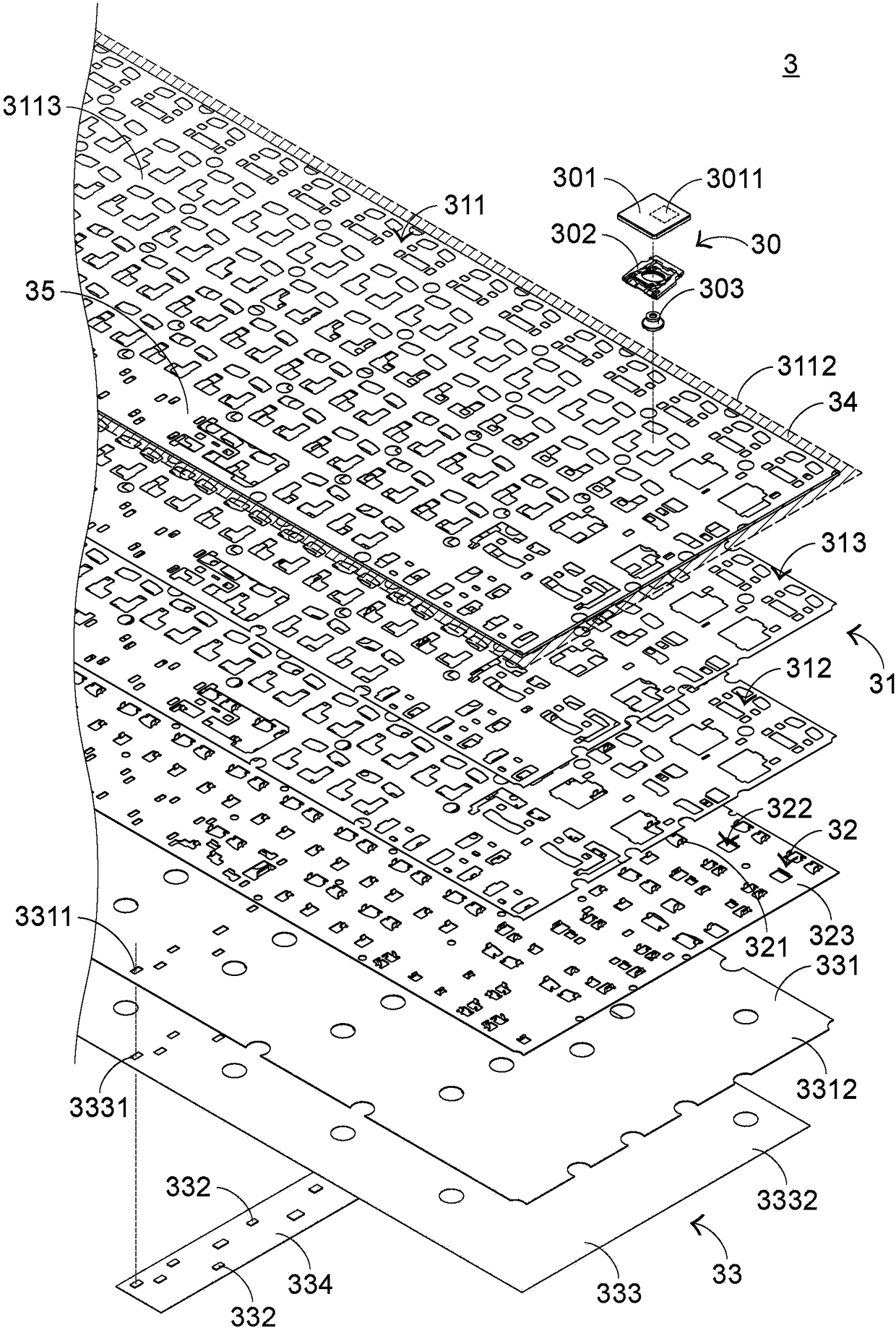
[0065] In view of the problems caused by the prior art, the present invention provides a luminous keyboard which can solve the problems of the prior art. First illustrate the structure of the luminous keyboard of the present invention, please refer to image 3 as well as Figure 4 , image 3 It is an exploded schematic diagram of the local structure of the luminous keyboard in the first preferred embodiment of the present invention, and Figure 4 It is a schematic cross-sectional view of a partial structure of the light-emitting keyboard in the first preferred embodiment of the present invention. The luminous keyboard 3 of the present invention includes a plurality of keys 30 , a membrane switch circuit 31 , a support plate 32 and a backlight module 33 , and the plurality of keys 30 are exposed outside the luminous keyboard 3 . The membrane switch circuit is disposed under the plurality of keys 30 , and its function is to generate corresponding key signals in response to th...


PUM


Abstract

The invention relates to a light-emitting keyboard, which comprises a plurality of keys, a thin film switch circuit, a support plate and a backlight module. The thin film switch circuit is arranged below the plurality of keys, and comprises an upper circuit board, a lower circuit board and a separating layer. The support plate is arranged below the thin film switch circuit and is connected to theplurality of keys. The backlight module is arranged below the support plate to generate light beams. The peripheral area of at least one of the upper circuit board, the lower circuit board and the separating layer is bent to cover the support plate and the backlight module to prevent the beams from overflowing from the peripheral area of the backlight module.

Description

technical field [0001] The invention relates to a keyboard, in particular to a luminous keyboard with a luminous function. Background technique [0002] Common computer peripheral input devices include a mouse, a keyboard, and a trackball. The keyboard can directly input text and symbols to the computer, so it is highly valued by users and input device manufacturers. [0003] see figure 1 , which is a schematic diagram of an appearance structure of an existing keyboard. There are a plurality of keys 10 on the surface of the existing keyboard 1, and these keys 10 are classified into general keys 101, number keys 102, and function keys 103, etc. These keys are pressed by the user's fingers to generate corresponding signals. The computer enables the computer to execute the pressed key functions, for example, the general key 101 is used to input symbols such as English letters, the number key 102 is used to input numbers, and the function key 103 is used to provide various fun...

Claims


Application Information

Patent Timeline
IPC IPC(8): H01H13/83
CPCH01H13/83H01H2219/064
Inventor 江英德陈柏安潘锦松徐振轩
Owner PRIMAX ELECTRONICS LTD
Why Eureka
Try Eureka