
Sheet Metal Parts Spraying System

A technology for sheet metal parts and pendants, applied in the field of sheet metal spraying systems, can solve the problems of affecting the spraying effect, insufficient dust removal of sheet metal parts, poor dust removal effect, etc., and achieve better spraying effect.

Active Publication Date: 2021-01-08
深圳市友信鑫五金制品有限公司
View PDF6 Cites 0 Cited by
  • Summary
  • Abstract
  • Description
  • Claims
  • Application Information

AI Technical Summary

Problems solved by technology

[0002] Sheet metal parts are relatively common hardware accessories. For example, electrical cabinets and cabinet doors are sheet metal parts. The spraying of sheet metal parts refers to the coating of corresponding paint on the surface of sheet metal parts to improve the use of sheet metal parts. Performance, after the sheet metal parts are polished, there is often a lot of powder or dust adhered to the surface. These powders and dust will produce a large number of dust spots on the sheet metal parts during the subsequent spraying operation, which will affect the spraying effect.
[0003] It is also possible to remove dust on the surface of sheet metal parts by setting a blowing room before spraying. Basically, it is simply to set an air blowing port in the blowing room for blowing and dust removal. bad

Method used


Image

  • Sheet Metal Parts Spraying System
  • Sheet Metal Parts Spraying System
  • Sheet Metal Parts Spraying System

Examples


Embodiment Construction

[0032] The present invention will be described in further detail below in conjunction with the accompanying drawings.

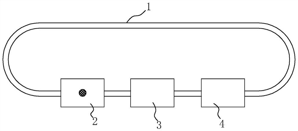
[0033] A sheet metal spraying system, such as figure 1 As shown, it includes a conveying chain 1 and a blowing chamber 2, a spraying chamber 3 and a drying chamber 4 arranged in sequence, wherein the conveying chain 1 is connected end to end to form a closed loop, and the sheet metal parts 24 are sequentially transported to the blowing chamber 2, spraying chamber 2 through the conveying chain 1 The chamber 3 and the drying chamber 4 perform dust removal, spraying and drying operations to complete the painting treatment on the surface of the sheet metal, wherein the conveyor chain 1 can be driven by a motor and a sprocket (not shown in the figure).

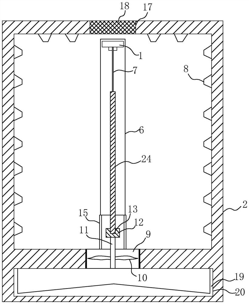
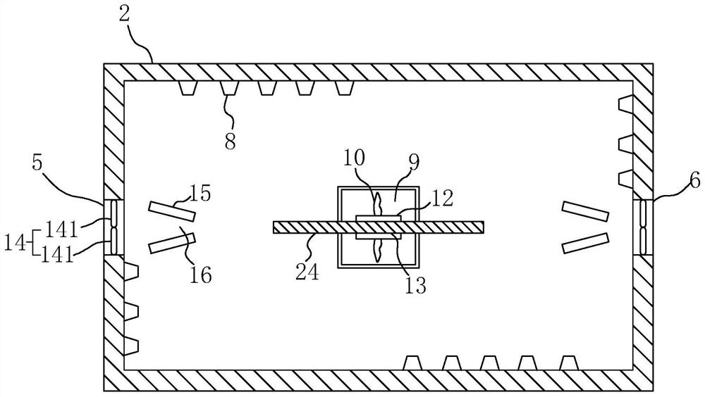
[0034] Such as figure 2 with image 3 , the two sides of the blowing chamber 2 are respectively provided with an inlet 5 and an outlet 6 for the sheet metal parts 24 to enter and exit, and a hanger 7 for the sh...


PUM


Abstract

The invention discloses a system for spraying a stamping part. The system comprises a conveying chain, an air blowing chamber, a spraying chamber and a drying chamber, wherein the air blowing chamber,the spraying chamber and the drying chamber are sequentially arranged; a hanging part which is used for hanging the stamping part is arranged on the conveying chain; air blowing holes are formed in the all side walls of the air blowing chamber; the air blowing holes formed in the opposite side walls of the air blowing chamber separately correspond to the different sides of the stamping part; thehanging part is rotatably connected with the conveying chain; an air suction hole is formed in the bottom of the air blowing chamber; an air blower is arranged in an air suction hole; a rotating shaftof the air blower extends into the air blowing chamber and a fixed bar is fixed; the fixed bar is provided with a strip groove through which the bottom end of the stamping part passes; the stamping part is blown through the air blowing holes formed in the different sides of the side walls of the air blowing chamber so that the stamping part is continuously rotated, and dust formed in the stampingpart is removed more comprehensively and completely; and moreover, in a rotation process of the stamping part, certain centrifugal force is also produced, and the dust is helpful to be blown off fromthe surface of the stamping part, so that the effect of the surface of the stamping part is better after subsequent spraying.

Description

technical field [0001] The invention relates to the field of sheet metal spraying, more specifically, it relates to a sheet metal spraying system. Background technique [0002] Sheet metal parts are relatively common hardware accessories. For example, electrical cabinets and cabinet doors are sheet metal parts. The spraying of sheet metal parts refers to the coating of corresponding paint on the surface of sheet metal parts to improve the use of sheet metal parts. Performance, after the sheet metal parts are polished, there is often a lot of powder or dust adhered to the surface. These powders and dust will produce a large number of dust spots on the sheet metal parts in the subsequent spraying operation, which will affect the spraying effect. [0003] It is also possible to remove dust on the surface of sheet metal parts by setting a blowing room before spraying. Basically, it is simply to set an air blowing port in the blowing room for blowing and dust removal. bad. Con...

Claims


Application Information

Patent Timeline
Patent Type & Authority Patents(China)
IPC IPC(8): B05B16/20B05B13/02B05B15/50
CPCB05B13/0264B05B15/50B05B16/20
Inventor 刘辉
Owner 深圳市友信鑫五金制品有限公司
Learn More