Heat recovery device for bath

A heat recovery device and heat recovery technology, applied in heat exchange equipment, heat exchanger types, indirect heat exchangers, etc., can solve the problem of not meeting the requirements for the use of instantaneous electric water heaters and the diameter of the power cord. , a lot of energy waste and other problems, to reduce power, improve the effect of heat energy absorption, reduce the effect of power loss

Inactive Publication Date: 2019-03-29
邝继伍
View PDF2 Cites 0 Cited by
  • Summary
  • Abstract
  • Description
  • Claims
  • Application Information

AI Technical Summary

Problems solved by technology

[0002] At present, instant electric water heaters are widely used. Due to their small size, fast heating, and no emissions, they are loved by many users. However, due to their high power, they are generally 6-8KW, and they need to use 4-6 mm 2 Copper wire, and the diameter of the power line of some users' homes does not meet this requirement, so it cannot be used
Especially in the houses built in the second and third tier cities before 2000, the diameter of some power lines is only 2.5mm. 2 , can not meet the requirements of instant electric water heater
Therefore, the promotion effect of instant electric water heaters is greatly limited. If the installation is not performed according to the requirements, the power of the installed water heater will be greater than the load carried by its power cord, and there will be potential safety hazards.
And in the water flow after bathing, there is a lot of heat energy, which is directly discharged as waste water, which is a great waste of energy

Method used


Image

  • Heat recovery device for bath
  • Heat recovery device for bath
  • Heat recovery device for bath

Examples


Embodiment Construction

[0022] The technical solutions in the embodiments of the present invention will be described in detail below in conjunction with the accompanying drawings in the present invention:

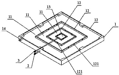
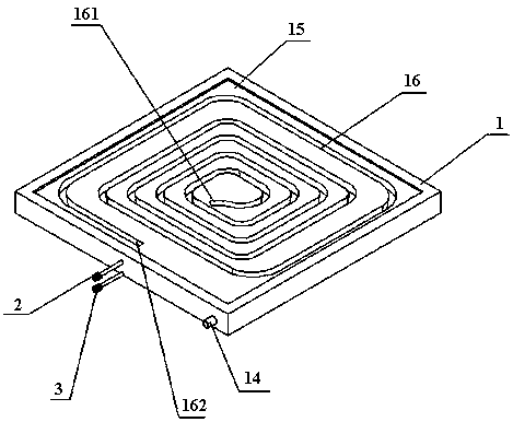
[0023] Such as figure 1 , figure 2 As shown, a heat recovery device for bathing in the present invention includes a heat recovery block 1, a sealing gasket 4, and a gland 5. The bottom surface of the heat recovery block 1 is provided with a water flow channel 16, and the water flow channel 16 is a spiral opening. The outer side of the water flow channel 16 is provided with a gasket 4, and the outer side of the gasket 4 is provided with a gland 5, and the gland 5 tightly presses the gasket 4 to the bottom surface of the heat recovery block 1 through a fastening device.

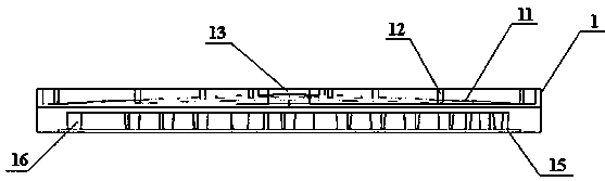
[0024] Such as figure 1 , figure 2 , image 3 , Image 6 As shown, the upper surface of the heat recovery block 1 is an arched surface 11 . The heat recovery block 1 is provided with a supporting column 12, and the supporti...


PUM


Abstract

The invention discloses a heat recovery device for bath. The heat recovery device for bath comprises a heat recovery block, a sealing gasket and a gland, wherein a water flow channel is formed in thebottom surface of the heat recovery block; the water flow channel is in the shape of an open spiral; the sealing gasket is arranged at the outer side of the water flow channel; the gland is arranged at the outer side of the sealing gasket; and the gland closely presses the sealing gasket onto the bottom surface of the heat recovery block through a fastening device. According to the heat recovery device for bath, the heat recovery block is adopted, and the spiral water flow channel formed in the heat recovery block and the heat recovery block are integrated; and concave-convex lines formed on the heat recovery block are capable of increasing the contact area of wastewater flow after bath, so that the purpose of improving the heat energy absorption effect for the heat recovery block is achieved. A filter arranged on the heat recovery block is capable of effectively controlling hair and other bath dirt after bath from entering into an arch-shaped surface of the heat recovery block. Because the water flow channel is formed by combining the sealing gasket and the gland, the water flow channel is capable of being detached and cleaned; and therefore, the heat recovery device for bath is energy-saving and environment-friendly, simple in structure, easy to clean, small in thickness, and capable of further meeting the user need.

Description

technical field [0001] The invention belongs to the technical field of heat recovery, and in particular relates to a heat recovery device for bathing. Background technique [0002] At present, instant electric water heaters are widely used. Due to their small size, fast heating, and no emissions, they are loved by many users. However, due to their high power, they are generally 6-8KW, and they need to use 4-6 mm 2 Copper wires, and the wire diameter of the power wires of some users' homes does not meet this requirement, so they cannot be used. Especially in the houses built in the second and third tier cities before 2000, the diameter of some power lines is only 2.5mm. 2 , can not meet the requirements for the use of instant electric water heaters at all. Therefore the promotional effect of instantaneous electric water heater is greatly limited, if not installed as required, the power of the installed water heater is greater than the load carried by its power cord, there w...

Claims


Application Information

Patent Timeline
Patent Type & Authority Applications(China)
IPC IPC(8): F28D1/047F28F19/01
Inventor 邝继伍
Owner 邝继伍
Why Eureka
Try Eureka