Centrifugal compressor air entraining structure and gas turbine engine

A centrifugal compressor, centrifugal impeller technology, applied in the direction of machine/engine, liquid fuel engine, mechanical equipment, etc., can solve the problem of reverse, aggravating influence, insufficient balance of centrifugal impeller, etc.

Active Publication Date: 2019-04-05
AECC HUNAN AVIATION POWERPLANT RES INST
View PDF7 Cites 6 Cited by
  • Summary
  • Abstract
  • Description
  • Claims
  • Application Information

AI Technical Summary

Problems solved by technology

The back chamber 5 of the centrifugal impeller 1 adopts the design method of radial inflow air induction, which intensifies the influence of the centrifugal force in the back chamber 5, increases the radial pressure drop of the back chamber 5, and reduces the average pressure of the back chambe...

Method used


Image

  • Centrifugal compressor air entraining structure and gas turbine engine
  • Centrifugal compressor air entraining structure and gas turbine engine
  • Centrifugal compressor air entraining structure and gas turbine engine

Examples


Embodiment Construction

[0038] Example embodiments will now be described more fully with reference to the accompanying drawings. Example embodiments may, however, be embodied in many forms and should not be construed as limited to the embodiments set forth herein; rather, these embodiments are provided so that this disclosure will be thorough and complete, and will fully convey the concept of example embodiments to those skilled in the art. The same reference numerals in the drawings denote the same or similar structures, and thus their detailed descriptions will be omitted.

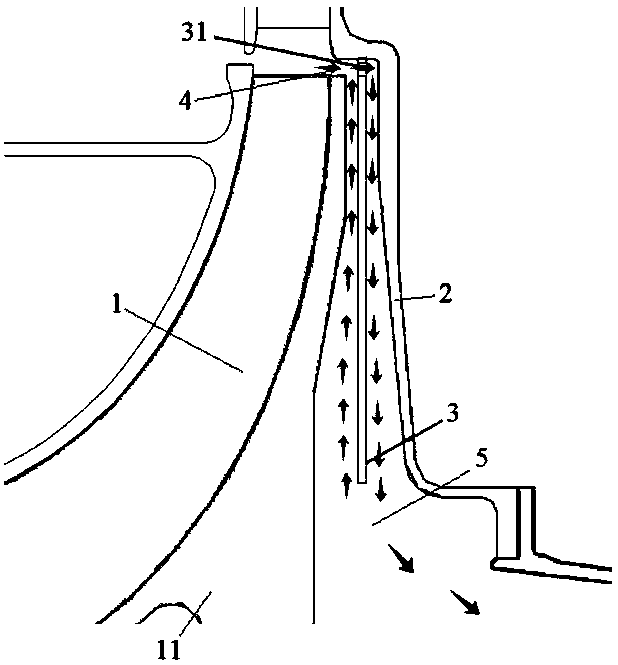
[0039] The present invention firstly provides a centrifugal compressor air-bleed structure, referring to image 3 The partial structural schematic diagram of the air-bleeding structure of the centrifugal compressor shown, the air-bleeding structure may include a centrifugal impeller disk 11, a baffle plate 2, and an annular diaphragm 3; the baffle plate 2 and the centrifugal impeller disk 11 form a static clearance 4 and a bac...


PUM


Abstract

The invention relates to the technical field of turbine engines, and provides a centrifugal compressor air entraining structure and a gas turbine engine. The air entraining structure comprises a centrifugal impeller disc, a baffle and an annular partition plate, the baffle and the centrifugal impeller disc form a stator gap and a back cavity, the stator gap communicates with the back cavity, the annular partition plate is connected to the baffle and located between the centrifugal impeller disc and the baffle, the annular partition plate is provided with a through hole right opposite to the stator gap so that airflow at an outlet of a centrifugal impeller can pass through the stator gap and the through hole to flow into the space between the annular partition plate and the baffle, airflowsurrounding the annular partition plate is formed, the flow direction of the airflow between the centrifugal impeller disc and the annular partition plate is outward in the radial direction, the coriolis force direction is opposite to the airflow tangential speed direction, influences of centrifugal force produced by airflow tangential movement are weakened, radial pressure drop of airflow of theback cavity can be reduced, the average static pressure of the back cavity can be increased, and therefore forward axial force of the back cavity of the centrifugal impeller disc is increased.

Description

technical field [0001] The invention relates to the technical field of turbine engines, in particular to a centrifugal compressor air-bleed structure and a gas turbine engine equipped with the centrifugal compressor air-bleed structure. Background technique [0002] When the aero-engine is running, in order to keep the tip clearance of the compressor motor blade at a small level and ensure the efficiency of the rotor blade, the axial force of the rotor is generally designed to be horizontal and forward, and the axial force of the rotor must not be light when the engine is running in different states The load is not reversed, so as not to damage the bearing and cause hazards. [0003] In small and medium-sized aviation gas turbine engines, the single-stage impeller design can achieve a large boost ratio by adopting the centrifugal impeller design, but the centrifugal impeller itself also has a large backward aerodynamic axial force, and the axial force of the back cavity of t...

Claims


Application Information

Patent Timeline
IPC IPC(8): F04D29/44F04D29/58F04D29/66
CPCF04D29/441F04D29/5846F04D29/662
Inventor 张远森周志翔喻雷
Owner AECC HUNAN AVIATION POWERPLANT RES INST
Why Eureka
Try Eureka