A capacitance and dielectric loss standard

A capacitance and standard device technology, applied in the direction of measuring electrical variables, instruments, measuring devices, etc., can solve the problems of unqualified dielectric loss testers, failure to measure test voltage, and reduce the accuracy level of standard devices, etc., to achieve high stability and cost performance , Realize real-time measurement and improve the effect of stability

Active Publication Date: 2021-02-26
任守华
View PDF9 Cites 0 Cited by
  • Summary
  • Abstract
  • Description
  • Claims
  • Application Information

AI Technical Summary

Problems solved by technology

[0013] (1) Capacitance is not adjustable: this standard has only one capacitor (100pF) available for use, and cannot provide capacitance options such as 500pF, 1nF, 10nF, 50nF, 100nF and 500nF, because the manufacture of large-capacity standard capacitors very difficult;
[0014] (2) The dielectric loss cannot be adjusted in real time with the frequency: according to formula (2), the dielectric loss of 10.000% at 50.00Hz will become 10.040% at 50.20Hz. This error will greatly reduce the accuracy level of the standard device, and may Cause the tested dielectric loss tester to be unqualified;
[0015] (3) The test voltage cannot be measured: the output voltage of the dielectric loss meter is one of the evaluation indicators of the dielectric loss meter. If the standard device can detect the high voltage output of the dielectric loss meter, it will greatly facilitate the verification work;
[0016] (4) No power frequency interference current can be applied: anti-power frequency interference is the basic function of the dielectric loss instrument. The current standard instrument cannot apply power frequency interference, and there is no simple method to simulate interference in the laboratory, so that the anti-interference of the dielectric loss meter Ability cannot be assessed

Method used


Image

  • A capacitance and dielectric loss standard
  • A capacitance and dielectric loss standard
  • A capacitance and dielectric loss standard

Examples


Embodiment 1

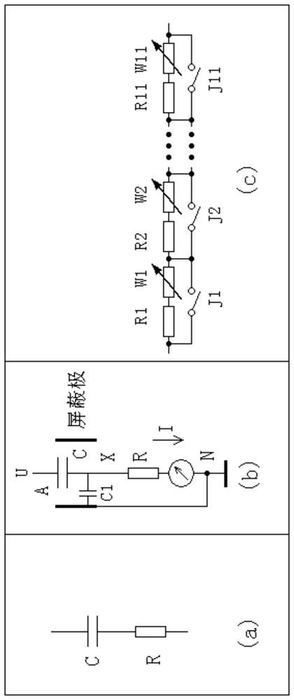
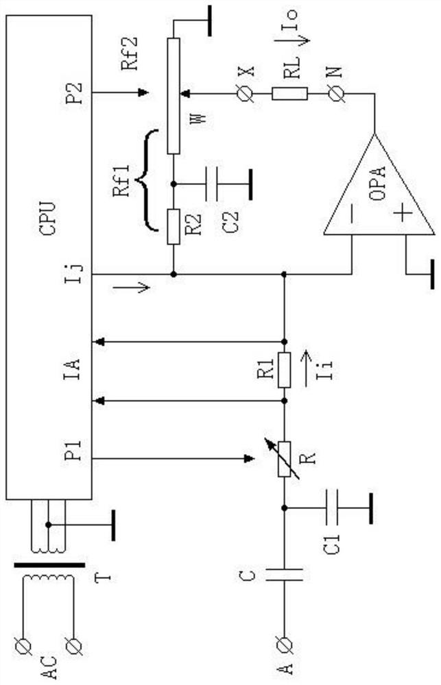
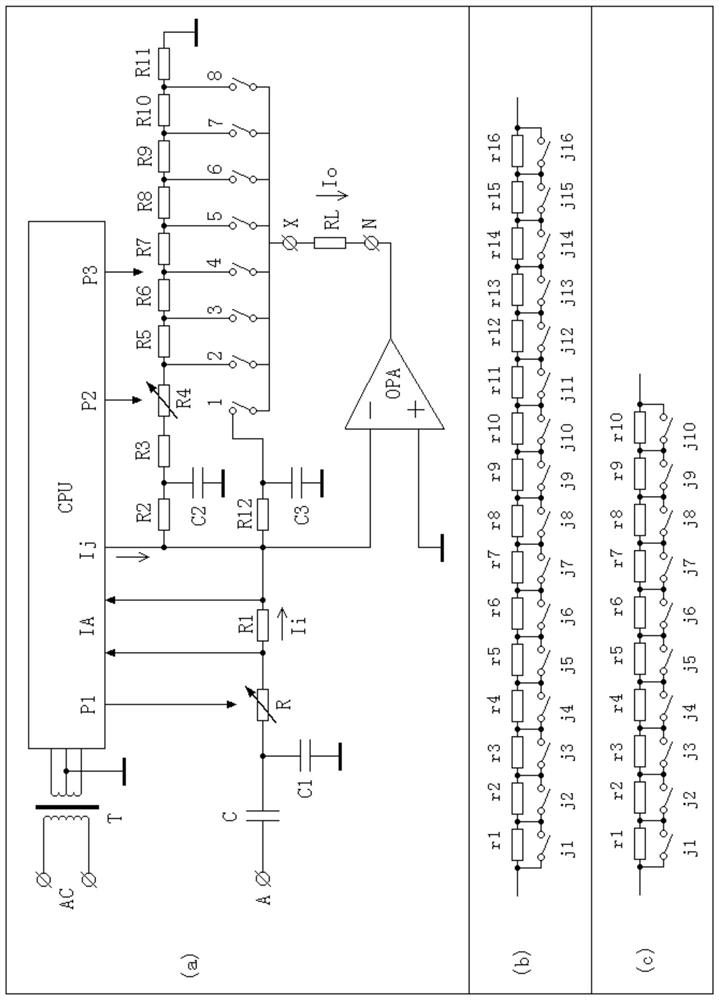
[0052] This embodiment provides a capacitance and dielectric loss standard, comprising a standard capacitor C, whose high-voltage terminal is connected to terminal A; compensation capacitor C1, whose first terminal is electrically connected to the low-voltage terminal of standard capacitor C, and whose second connection The terminal is connected to the power supply ground; the first terminal of the adjustable resistor R is electrically connected to the low-voltage terminal of the standard capacitor C; the sampling resistor R1 is electrically connected to the second terminal of the adjustable resistor R; the operational amplifier OPA , its positive input terminal is connected to the power ground, its negative input terminal is electrically connected to the second terminal of the sampling resistor R1, and its output terminal is connected to the common terminal N; the lead compensation resistor R2, its first terminal is connected to the negative input of the operational amplifier O...


PUM

PropertyMeasurementUnit
electrical resistanceaaaaaaaaaa

Abstract

The invention discloses a capacitance and dielectric loss standard instrument, and belongs to the field of power equipment capacitance and dielectric loss factor measurement. The capacitance and dielectric loss standard instrument aims to solve the technical problems that how to realize multiple adjustable capacitance, the dielectric loss can be adjusted in real time along with the frequency, a test voltage can be measured and a power frequency interference current can be applied. The capacitance and dielectric loss standard instrument structurally includes a standard capacitor C, an adjustable resistor R and a compensation capacitor C1, a sampling resistor R1, an operational amplifier OPA, a lead compensation resistor R2, a lead compensation capacitor C2, an adjustable resistor network W,a controller CPU and a power transformer T. The standard instrument has the functions of the multiple adjustable capacitance, real-time adjustment of the dielectric loss along with the frequency, thetest voltage capable of being measured and the power frequency interference current capable of being applied. Compared with a traditional standard instrument, the capacitance and dielectric loss standard instrument can more comprehensively and conveniently verify a dielectric loss meter.

Description

technical field [0001] The invention relates to the field of electric equipment capacitance and dielectric loss factor measurement, in particular to a capacitance and dielectric loss standard. Background technique [0002] Capacitance and dielectric loss factor (hereinafter referred to as dielectric loss) are important indicators of capacitors or power capacitive equipment. Dielectric loss factor measuring instrument (hereinafter referred to as dielectric loss meter) is a conventional instrument for measuring capacitance and dielectric loss. Capacitance and dielectric loss standards are needed in the instrument. [0003] Resistor R and capacitor C are connected in series, such as figure 1 As shown in (a), its equivalent dielectric loss is: [0004] tgδ=ωCR (1) [0005] ω=2πF, F is the measurement frequency, generally refers to the power grid frequency 50HZ. The actual situation is that if R is configured according to formula (1), the dielectric loss is always too large. ...

Claims


Application Information

Patent Timeline
Patent Type & Authority Patents(China)
IPC IPC(8): G01R35/00
CPCG01R35/007
Inventor 任守华任翔
Owner 任守华
Why Eureka
Try Eureka