
Operational Amplifier Frequency Compensation Circuit

An operational amplifier and frequency compensation technology, applied in amplifiers, differential amplifiers, DC-coupled DC amplifiers, etc., can solve the problems of reducing the unity gain bandwidth of the operational amplifier, reducing the -3dB bandwidth, etc., to improve the unity gain bandwidth and increase the voltage swing. rate, the effect of optimizing the large-signal response characteristics

Active Publication Date: 2019-02-19
NO 24 RES INST OF CETC
View PDF4 Cites 0 Cited by
  • Summary
  • Abstract
  • Description
  • Claims
  • Application Information

AI Technical Summary

Problems solved by technology

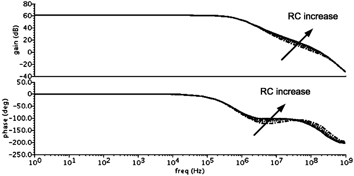
However, the traditional frequency compensation technology usually obtains the ideal phase margin by reducing the frequency of the dominant pole in the frequency domain through pole splitting, but this will reduce the -3dB bandwidth, thereby greatly reducing the unity gain bandwidth of the operational amplifier.

Method used


Image

  • Operational Amplifier Frequency Compensation Circuit
  • Operational Amplifier Frequency Compensation Circuit
  • Operational Amplifier Frequency Compensation Circuit

Examples


Embodiment Construction

[0020] In order to enable those skilled in the art to better understand the technical solutions in the embodiments of the present invention, and to make the above-mentioned purposes, features and advantages of the embodiments of the present invention more obvious and understandable, the following describes the technical solutions in the embodiments of the present invention in conjunction with the accompanying drawings For further detailed explanation.

[0021] In the description of the present invention, unless otherwise specified and limited, it should be noted that the term "connection" should be understood in a broad sense, for example, it can be a mechanical connection or an electrical connection, or it can be the internal communication of two elements, it can be Directly connected or indirectly connected through an intermediary, those skilled in the art can understand the specific meanings of the above terms according to specific situations.

[0022] see figure 1 , is a ...


PUM


Abstract

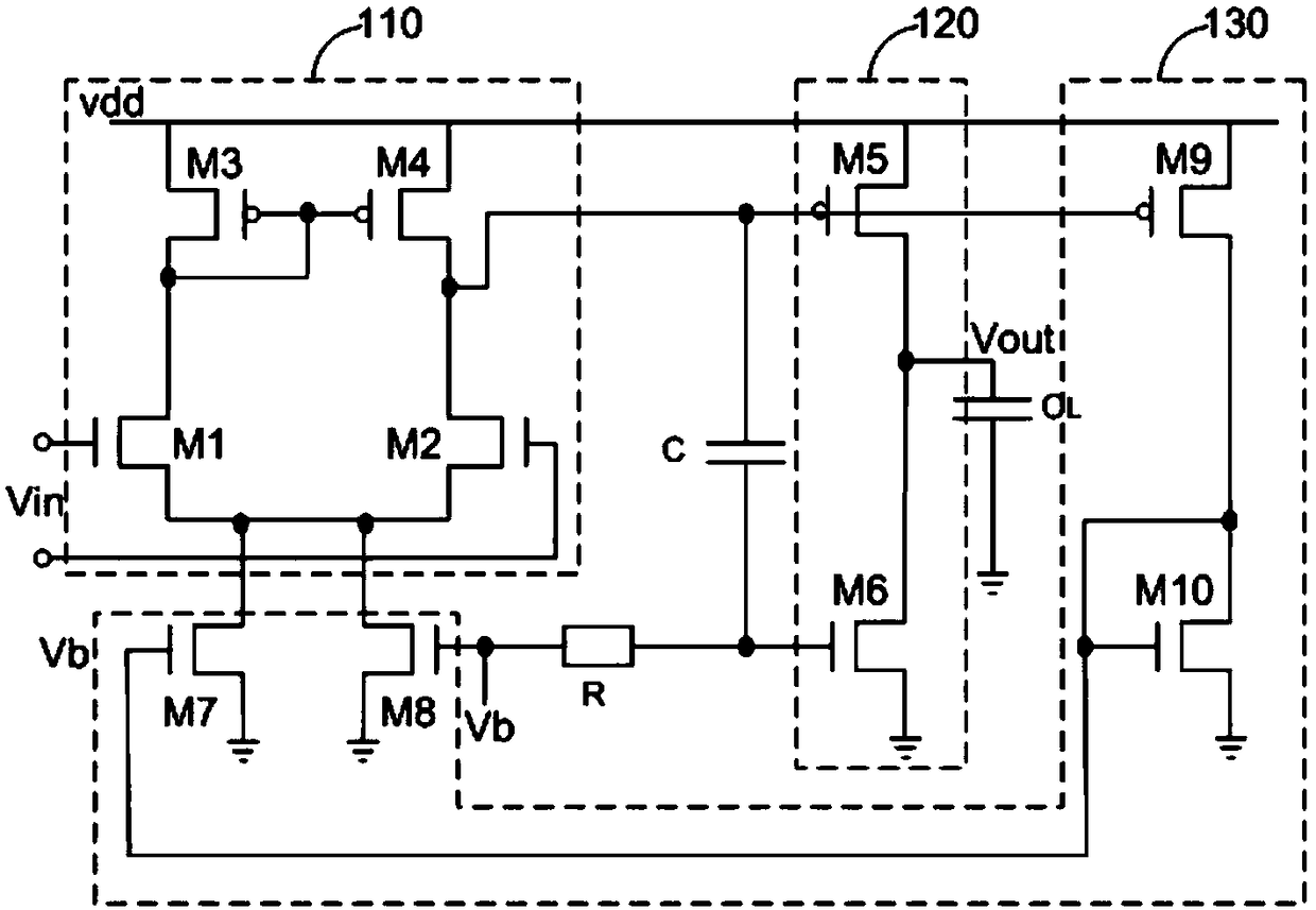
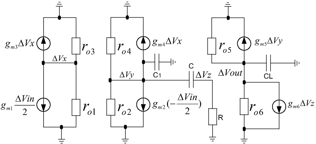
The invention provides a frequency compensation circuit for an operational amplifier. The frequency compensation circuit comprises a gain circuit, an output circuit and a tail current source bootstrap circuit of the gain circuit, wherein a grounding end of the gain circuit is connected with a first end and a second end of the tail current source bootstrap circuit; an output end of the gain circuit is connected with a first input end of the output circuit and an input end of the tail current source bootstrap circuit respectively; an output end of the tail current source bootstrap circuit is connected a bias voltage, and connected with a second input end of the output circuit through a first resistor; and the second input end of the output circuit is connected with the output end of the gain circuit through a first capacitor. Based on an RC network consisting of the first resistor and the first capacitor, the operational amplifier generates a left-half plane null point z, and the left-half plane null point z and a first non-main pole of the operational amplifier can be counteracted by adjustment of the magnitude of the RC, so that frequency compensation of the operational amplifier is realized. Meanwhile, the unit gain bandwidth of the operational amplifier can be increased remarkably.

Description

technical field [0001] The invention belongs to the field of analog or digital-analog hybrid integrated circuits, and in particular relates to an operational amplifier frequency compensation. Background technique [0002] In recent years, with the continuous development of integrated circuit design technology, more and more operational amplifiers are used in the field of analog integrated circuit design. The performance of an operational amplifier mainly depends on two aspects. One aspect is small-signal AC performance, including gain , bandwidth and phase margin, etc.; another aspect is the large signal response speed, mainly the voltage slew rate. From the perspective of small-signal AC performance, in most applications of operational amplifiers (especially transconductance amplifiers), in order to obtain a large phase margin of the operational amplifier and ensure the stability of the operational amplifier, the frequency of the operational amplifier will be adjusted. com...

Claims


Application Information

Patent Timeline
Patent Type & Authority Patents(China)
IPC IPC(8): H03F3/45
CPCH03F3/45183H03F2203/45631
Inventor 徐代果胡刚毅李儒章王健安陈光炳王育新付东兵刘涛刘璐邓民明石寒夫王旭
Owner NO 24 RES INST OF CETC
Learn More